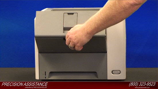
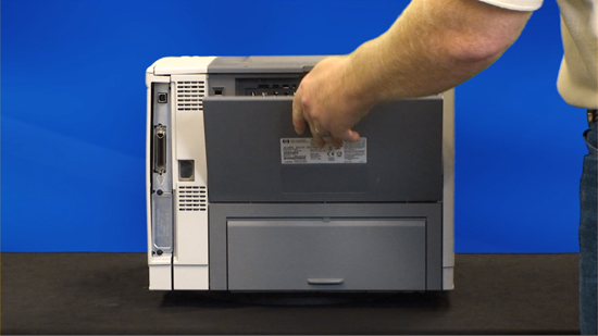
Before Installation:
Turn the power off and unplug the power cord from the printer.
Caution if you have been using the printer the fuser section will be hot! Please allow the fuser to cool for at least 30 minutes before removing it.
Removing the transfer roller
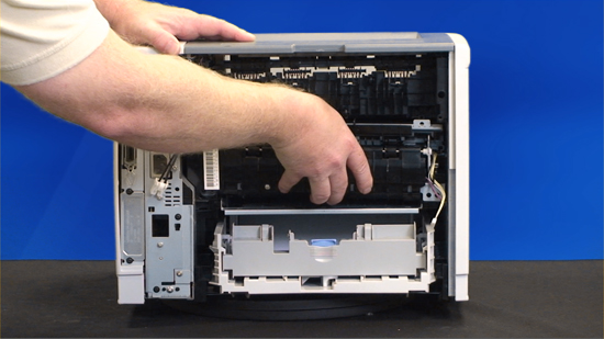
With the printer facing toward you, open the cartridge door and remove the toner cartridge.
Release the left end of the transfer roller by pinching the tabs on the transfer roller bushing, the use of needle-nose pliers or a small flat blade screwdriver to pinch two tabs may be necessary.
Once the tabs are released lift the transfer roller shaft out of the printer.
Installing the transfer roller
Caution please be careful not to touch the surface of the new transfer roller. Oils from your skin can adversely affect print quality.
Insert the right end of the transfer roller into the printer; secure the metal tip into its black retaining clip.
Install the left end of the transfer roller – ensure to line up the grooves in the bushing with the ridges and gently push the white bushing down to lock it into place.
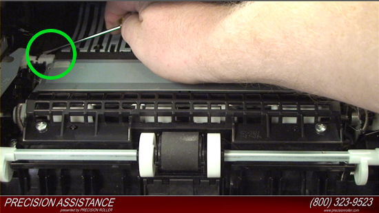
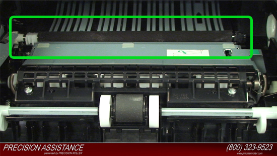
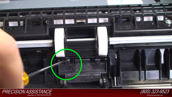
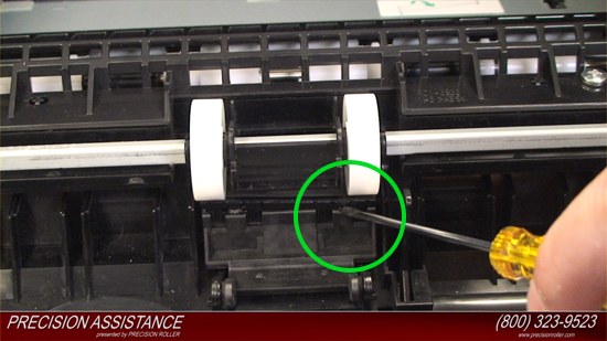
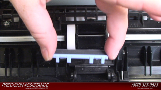
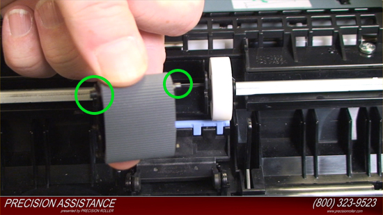
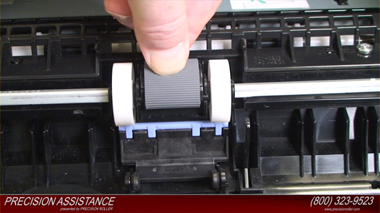
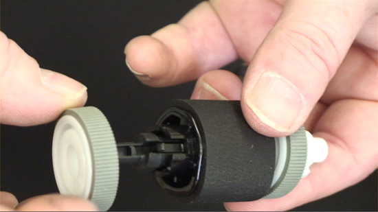
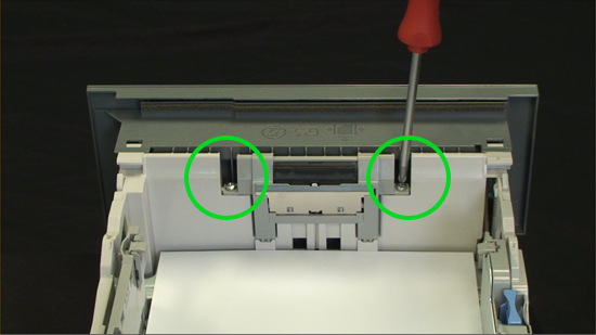
Removing Tray 1 D Shaped Pickup Roller Multi- Purpose (MP) Tray
You will find the tray 1 pickup roller & separation pad directly in the center of the machine.
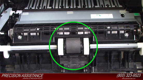
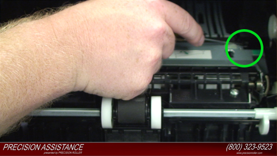
Spread the pickup-roller locks on each side with your fingernails or with a standard screw driver of the tray 1 pickup roller to release the roller.
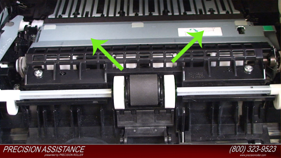
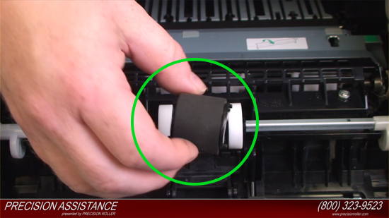
Rotate the top of the roller off of the shaft, and then lift the roller out of the device.
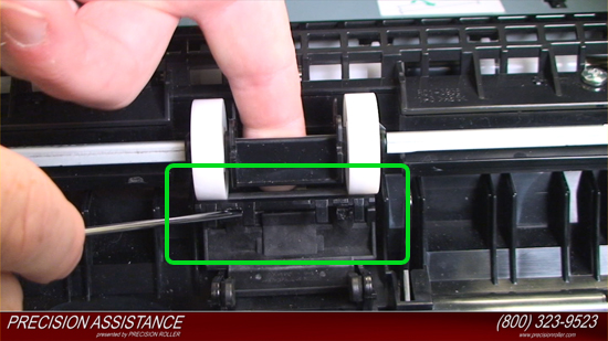
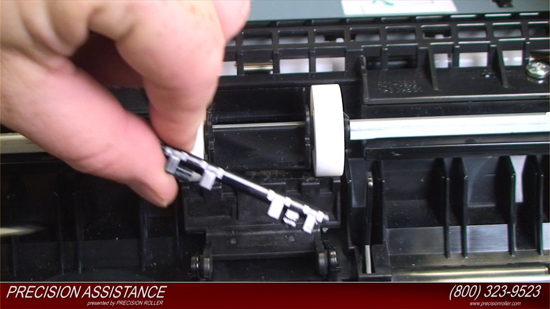
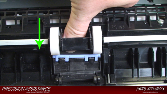
Removing Tray 1 Separation Pad
Insert a flat blade screwdriver into the opening underneath the separation pad to gently pry the pad up from the left then the right side and free it from its base. Once the pad is loose, remove it from the printer.
Install Tray 1 Separation Pad
With the Multi- Purpose (MP) Tray open insert the new separation pad onto the base.
Press down firmly on the left until it locks into place then press down firmly on the right side until it locks into place. A flat blade screwdriver may be needed to securely lock both sides of the new separation pad into place.

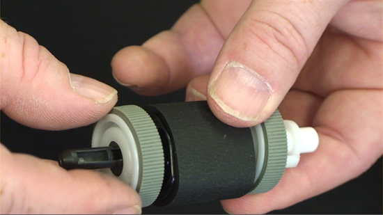
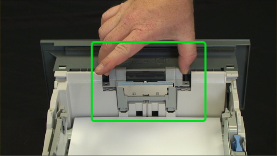
Installing Tray 1 D Shaped Pickup Roller Multi- Purpose (MP) Tray
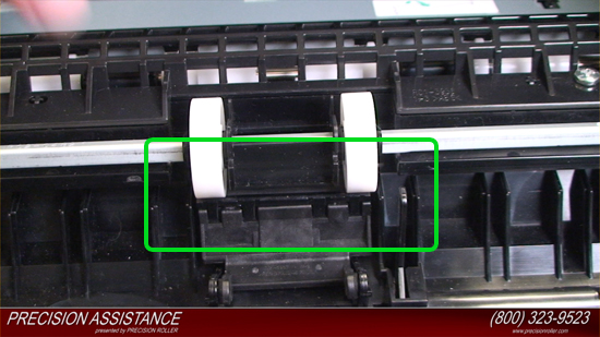
Install the new pickup roller by inserting it into the empty slot you removed it from.
You will notice a small round peg on both sides and a small notch.
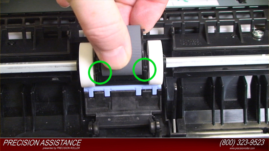
Line up the round peg with its hole on the empty slot you removed it from and press down on the pickup roller so the notch locks into place.
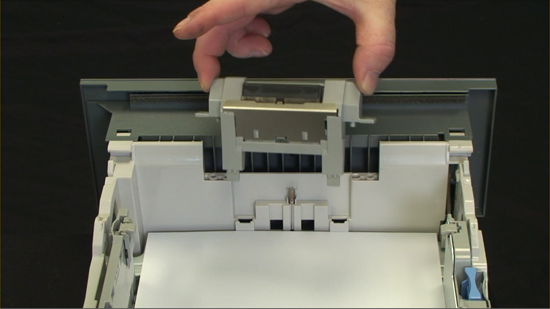
Install the toner cartridge into the printer and close the door to tray 1.
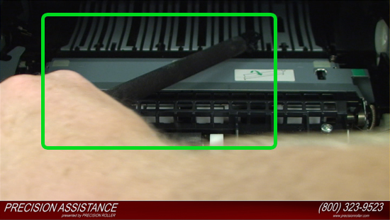
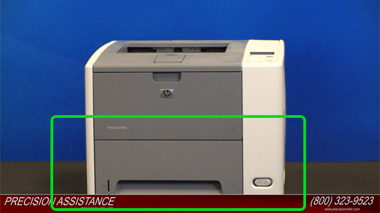
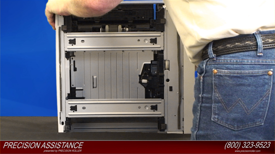
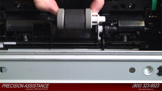
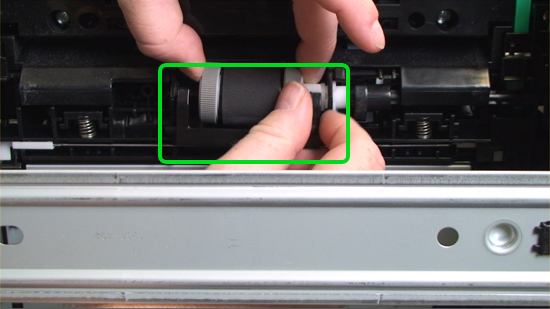
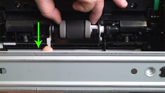
Removing the Tray 2 Pickup Roller
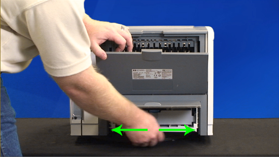
Remove tray 2 from the printer.
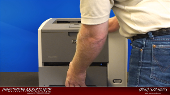
Tip the device over on its rear side, with the bottom of the device facing you so you can easily access the tray 2 pickup roller.
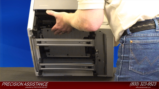
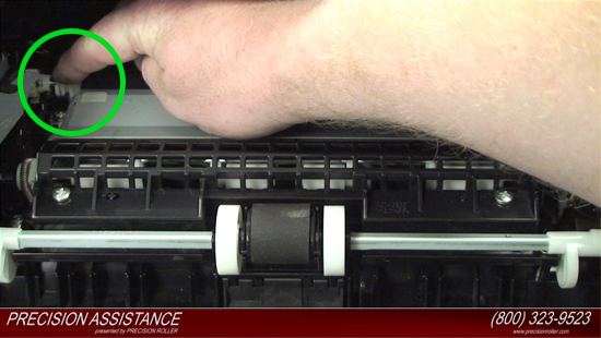
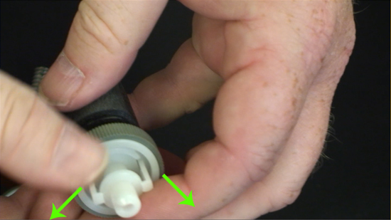
Gently release the white plastic lever on the left side of the pickup roller with a flat blade screw driver or your finger, and rotate the white plastic lever outwards.
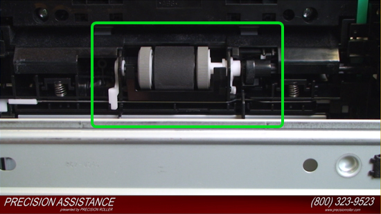


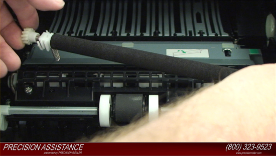
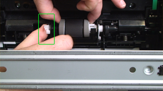
Slide the roller and shaft toward the left until they clear the hole in the right-side bushing, and then lift the right end of the shaft.
Remove the black plastic guide which sits just below the roller, blocking access.
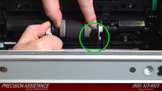
Slide the roller and shaft toward the right, and then lift the roller and shaft together out of the device.
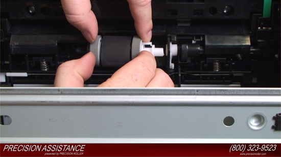
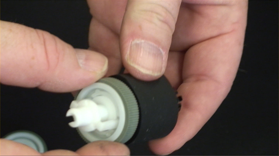
Remove the feed tires then - Press this tab to release and remove the black shaft.
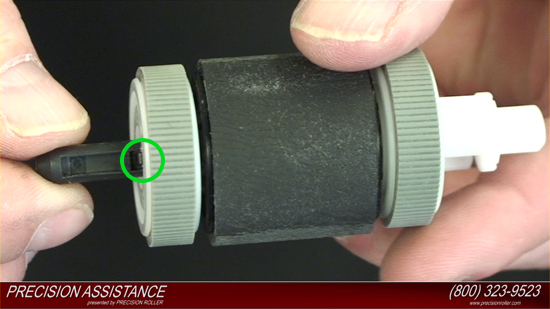


With the shaft removed, tilt the roller so the spring falls out.


Installing the Tray 2 Pickup Roller
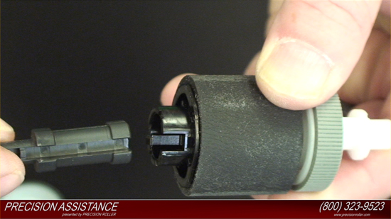
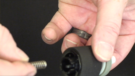
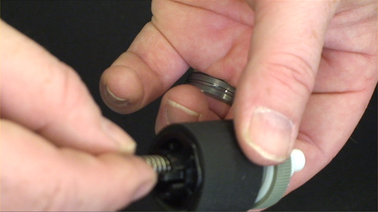
Reassemble the roller assembly by inserting the spring into the new pickup roller empty shaft, reinstall the shaft to the pickup roller and Reinstall the feed tires.

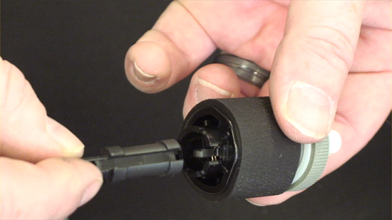

Reinstall the newly assembled pickup roller by sliding it into the empty slot you removed it from. Install the black plastic guide which sits just below the roller – Reinstall the white plastic lever and gently lock it into place.


Tip the device so that it sits normal.
Install the toner cartridge into the printer and close the door to tray 1.
Removing Tray 2 separation Pad
Pull tray 2 out of the device.
Remove two screws from the separation-pad assembly.
Lift the assembly out of the tray.
Install Tray 2 separation Pad
Install the new separation pad by sliding it into the empty slot you removed it from.
Install the two screws to hold the separation-pad assembly into place.
Install tray 2 into the printer.
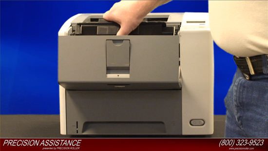
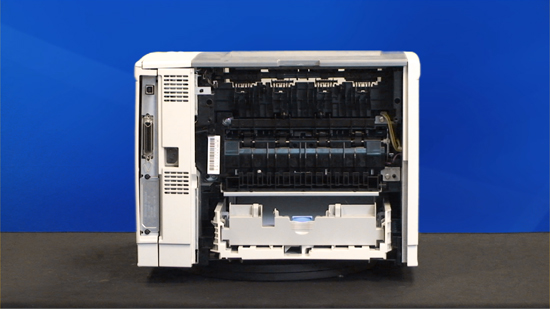
Removing the Fuser
Open the rear output bin door, press the door down to disengage the two door stops - remove the two screws that holds the back cover on .
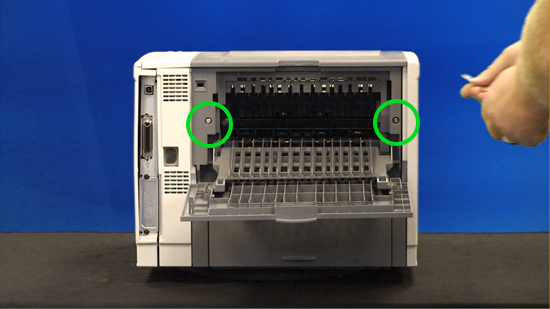
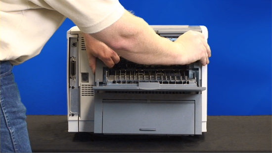
Lift the bottom of the cover first to disengage the alignment tabs at the top of the back cover, and then lift the cover away from the device.
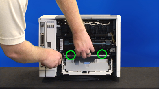
Remove the duplexer inlet guide by releasing two tabs on the guide with a standard screw driver, and then sliding the guide toward the back of the device and remove it.
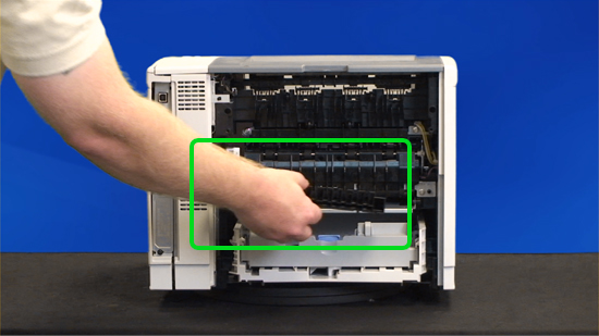
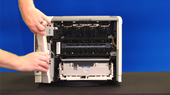
Pry off the white plastic side cover to the left to remove it.
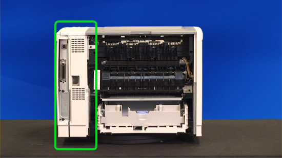
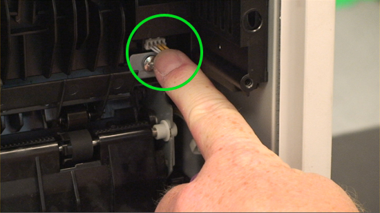
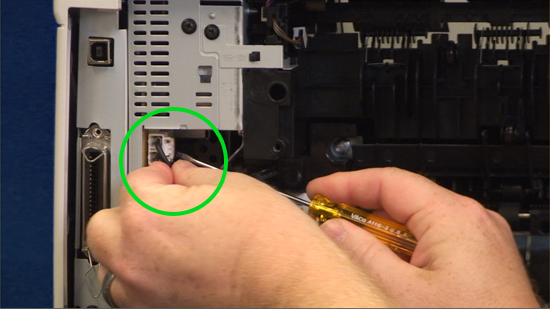
Disconnect two cables at the right, inside, of the device.

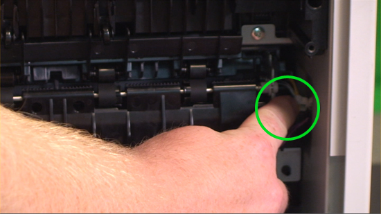
Disconnect the fuser power cable at the left side of the device.
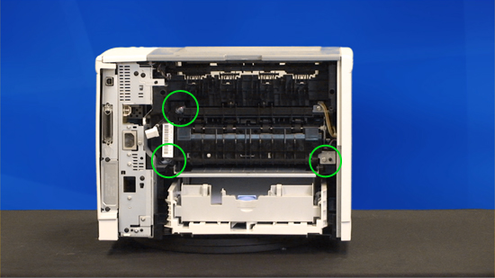
Remove three self-tapping screws and one grounding screw with a Phillips screw driver.
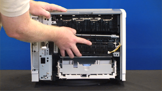
Tilt the fuser slightly toward the back of the device, and then slide the fuser out of the back of the printer.
Installing the fuser
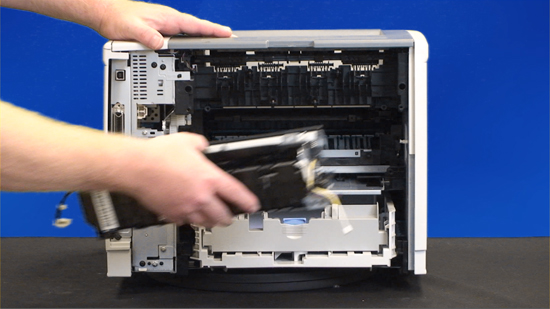
Install the new fuser by sliding it in and tilting it slightly until it locks into place.
Install the three self-tapping screws and one grounding screw.
Install the two cables at the right, inside, of the device, and then install the fuser power cable at the left side of the device.
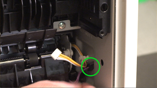
Attach the longer of the two wires to the open clip and close the clip to keep the wire secure.
Install the white plastic side cover.
Install the duplexer inlet guide sliding the guide toward the back of the device.
Install the rear output bin door and align the tabs until they snap into place.
Install the two screws and close the rear output bin door.
Resetting the maintenance count
Plug the power cord into the printer and Turn the printer on.
When the memory count begins, press and hold the checkmark button. Continue holding down the checkmark button until all three device control-panel lights flash once and then remain on. This might take up to 10 seconds.
After the message SELECT LANGUAGE appears on the display, press the up or down arrow button until COLD RESET is highlighted and press the checkmark button.
The device performs a cold reset and then continues its power-on sequence.


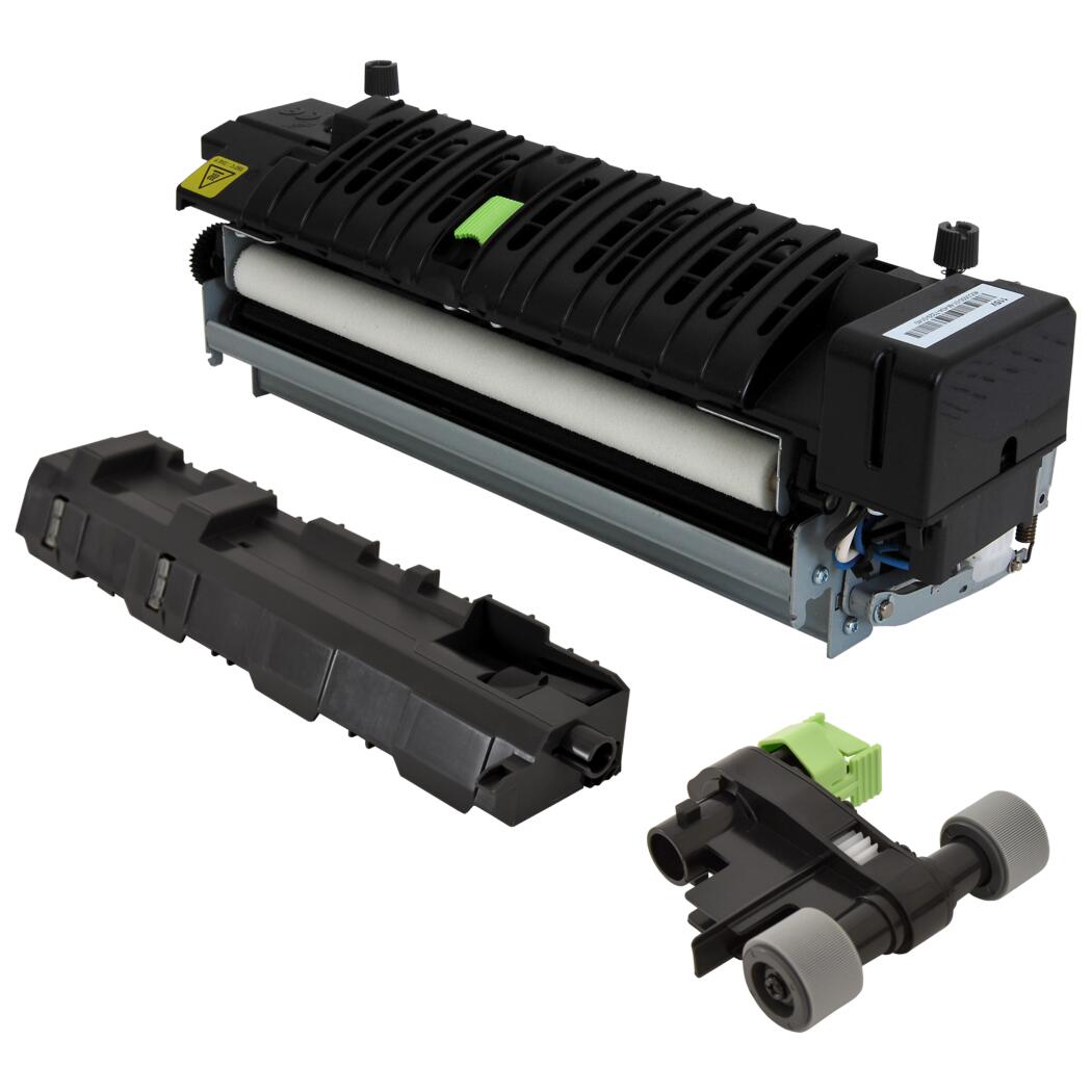 Lexmark Fuser Maintenance Kit - Type 00


