


|
HP LaserJet 4250 Maintenance Kit Instructions
Originally written for: HP LaserJet 4250
Also applies to: HP LaserJet 4250dtn, 4250dtnsl, 4250n, 4250tn, 4350dtn, 4350dtnsl, 4350n, 4350tn

These instructions will help explain maintenance kit installation steps for an HP LaserJet 4250 and similar models. To order your replacement maintenance kit for this printer, use the following part: G8839 (HP Q5421A) Before installing the maintenance kit:
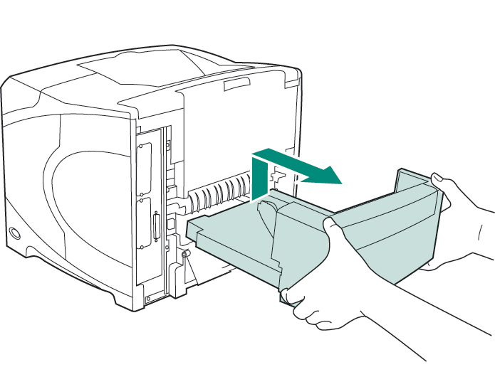
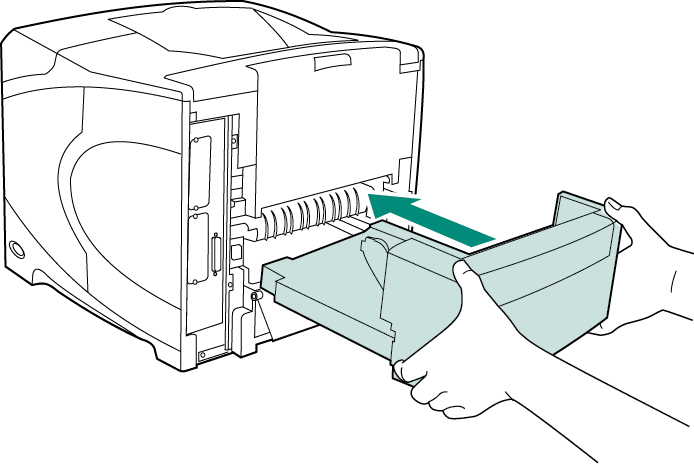
Rotate the printer so that its rear cover faces you. Lift and pull to remove the optional duplexer, if it is installed.
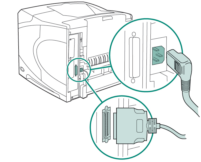
Disconnect all cables from the rear of the printer.
To replace the transfer roller:
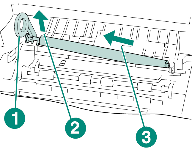
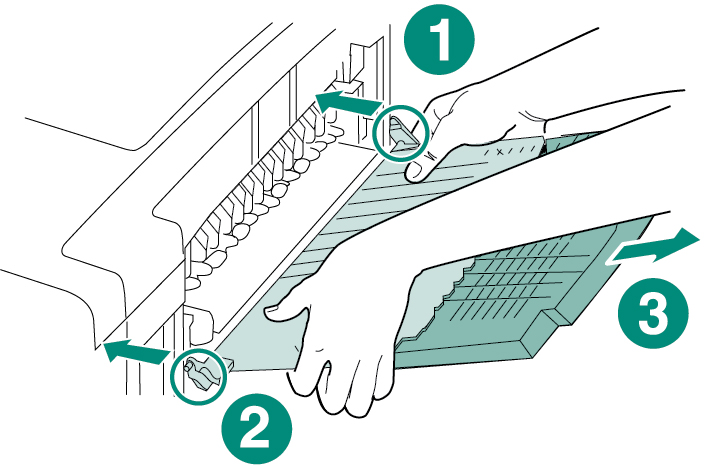
CAUTION: Do not lift the left end of the transfer roller too far when removing the transfer roller. Use the plastic transfer-roller tool (callout 1) to slightly lift the left end of the metal shaft upward (callout 2). Slide the transfer roller to the left and remove it (callout 3).
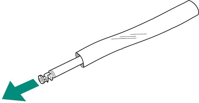
CAUTION: Do not touch the replacement transfer roller with bare hands. Skin oils on the roller can cause print-quality problems. Put on the gloves and remove the replacement transfer roller from the protective bag.
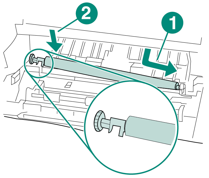
Make sure that the black collar on the left side is oriented properly, with the open end down. Install the new transfer roller by sliding the right side into place (callout 1). Snap the left side (with the gear) into place (callout 2).
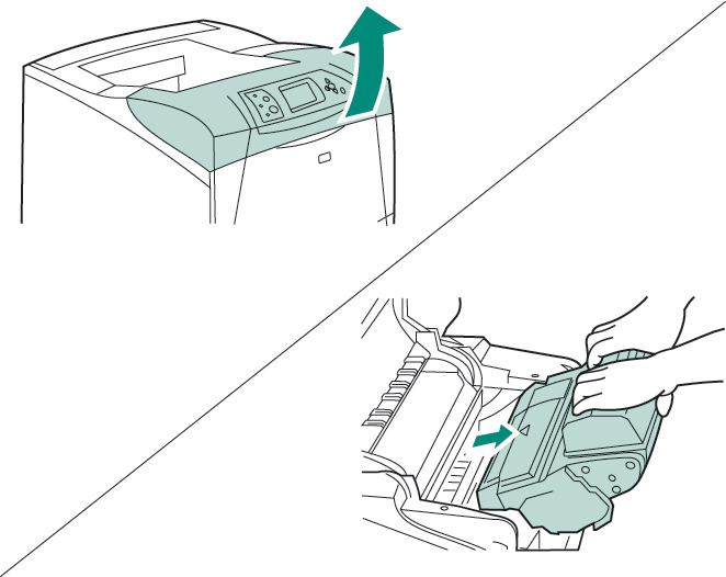
Install the print cartridge, then close the top cover.
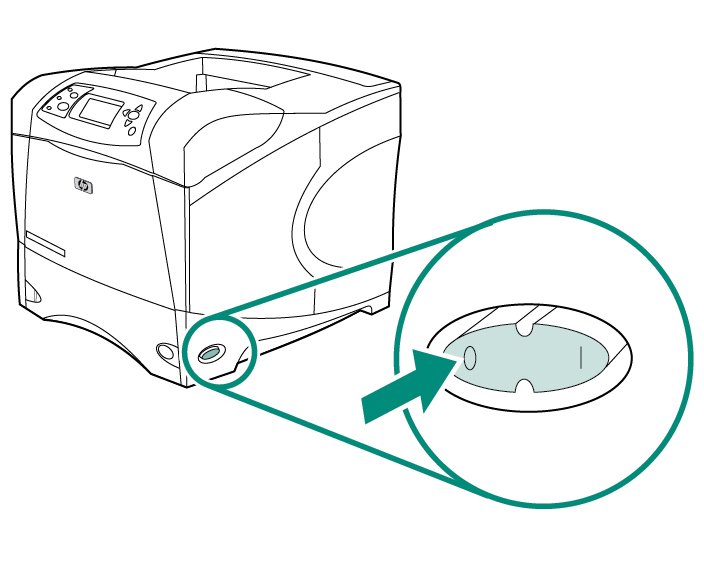
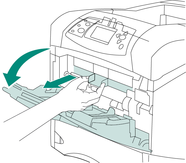
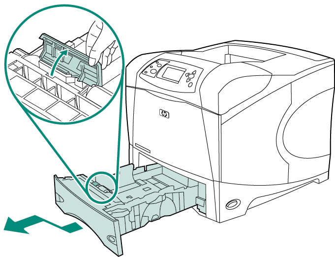
To replace the tray 1 pickup roller:
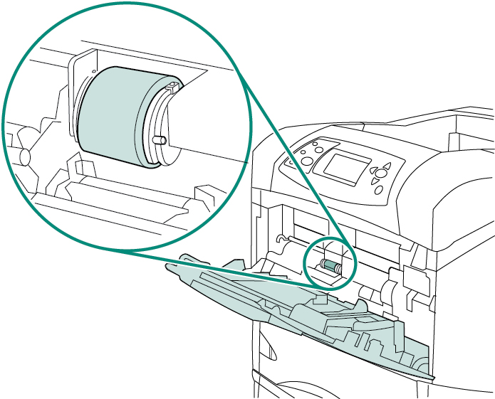
Locate the pickup roller at the center of tray.
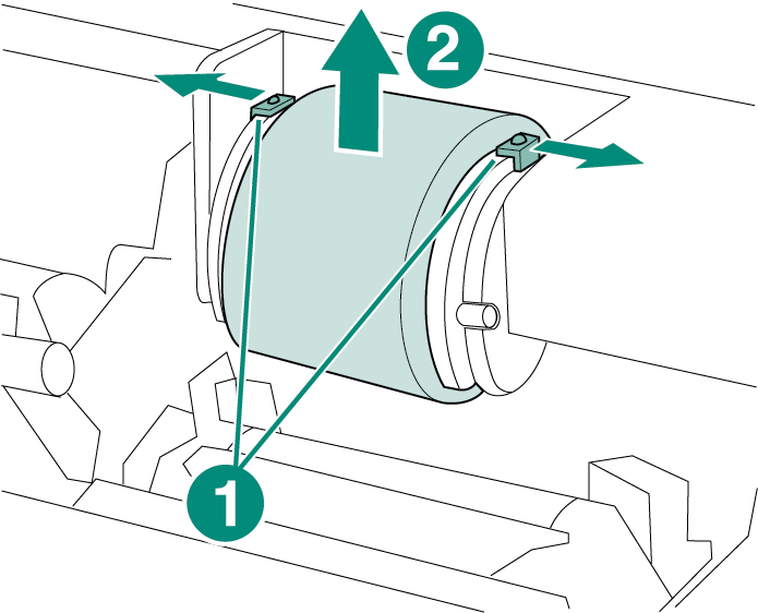
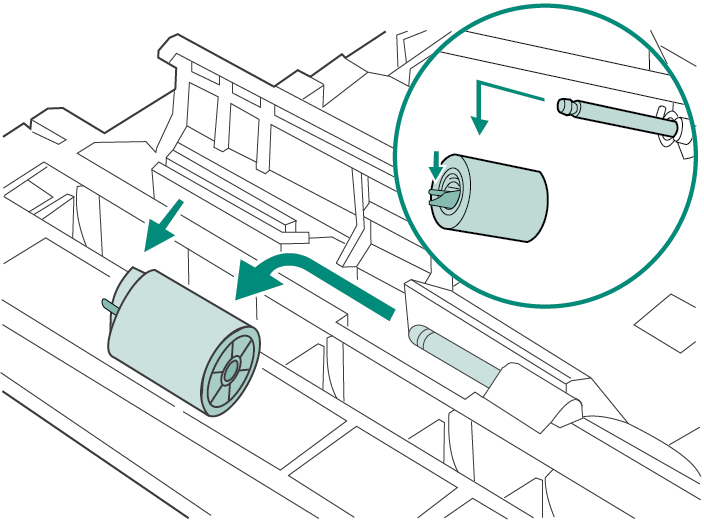
Release the roller by sliding apart the two latches located on each side at the top of the pickup roller (callout 1). Lift the roller out of the opening (callout 2).
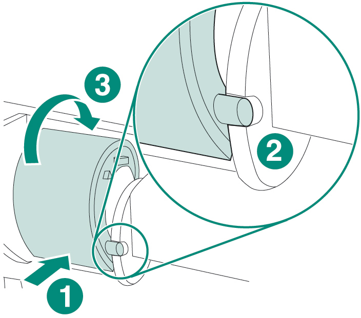
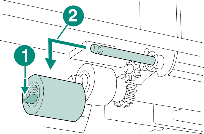
Place the new pickup roller onto the shaft (callout 1). Align the pin that is located on each side at the bottom of the roller with the slot in the bracket located on each side of the opening (callout 2). Slide the roller into the printer until the roller snaps into place (callout 3).
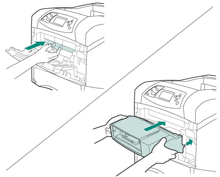
Insert the front accessory cover.
To replace the tray 2 feed and separation rollers:
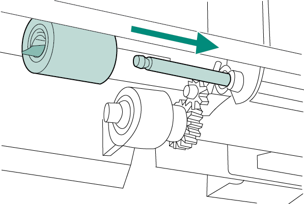
Push the blue latch that is on the left side of the feed roller away from the roller shaft to unlock the roller. Slide the roller off of the shaft.
Slide a new feed roller onto the shaft.
WARNING! Do not allow the front of the printer to extend beyond the edge of the table. The printer can become unbalanced and fall, causing damage or injury. Move the front of the printer to the edge of the table top for better access to the feed roller that is located inside of the printer.
Push the blue latch on the left side of the feed roller (callout 1) away from the roller shaft to unlock the roller. Slide the roller off of the shaft (callout 2). You might need to rotate the roller in order to unlock the latch.
Slide a new feed roller onto the shaft and rotate the roller until it locks into place.
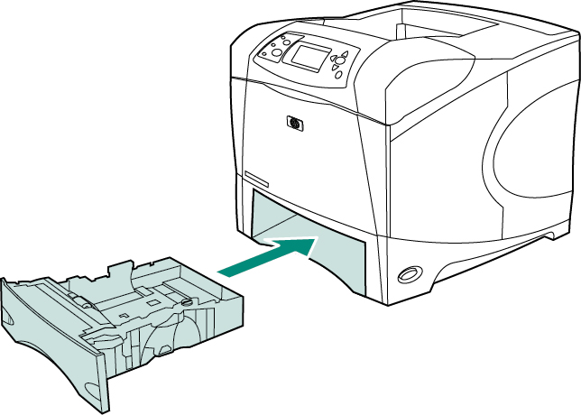
Insert tray 2.
Remove the rear output bin and extension by pushing the left side hinge toward the right side of the printer until the hinge clears the mounting hole in the printer chassis. Rotate the left side of the output bin and extension away from the printer and remove the output bin and extension.
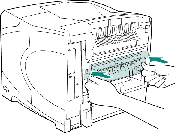
WARNING! The fuser might be hot. Make sure that the printer has been turned off for a minimum of 30 minutes before removing the fuser. Locate the blue fuser release levers on each side of the fuser. Pinch the blue levers upward and pull the fuser straight out of the printer.
Push the new fuser firmly into the printer until the blue levers on both sides click into place.
Install the rear output bin. Insert the right hinge pin in the hole in the chassis. Push the left side of the output bin toward the right side of the printer. Slide the left hinge into the printer until the left hinge pin is inserted into the hole in the chassis. Pull gently on the output bin to make sure that the hinge pins are fully inserted.
Install the optional duplexer, if it was removed.
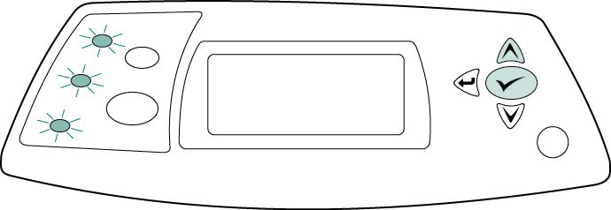
To finish the installation: Turn the printer power on. When the message XXXMB appears on the control-panel display, press and hold down √ (check mark) for several seconds, until all three control panel lights turn on and remain on. Press ^ (up arrow) until the NEW MAINTENANCE KIT message appears on the display, and then press √ (check mark).
|


 Lexmark Black High Yield Toner Cartridge


©2003-2026 Precision Roller. • 2102 West Quail Avenue, Suite 1 • Phoenix, AZ 85027 • (800) 323-9523 / (623) 581-3330 • M-F 7:30am - 5:00pm MST (noDST)
Individual brands are copyrighted by their respective owners. Precision Roller is in no way affiliated, sponsored or endorsed by these copyright owners or their affiliates or dealers.
This website uses a secure server to encrypt all sensitive information.
Questions? Concerns? Send us a note at webmaster@precisionroller.com
This website uses a secure server to encrypt all sensitive information.
Questions? Concerns? Send us a note at webmaster@precisionroller.com