

|
HP Color LaserJet 3600 Maintenance Kit Instructions
Originally written for: HP Color LaserJet 3600
Also applies to: HP Color LaserJet 3000, 3000dn, 3000dtn, 3000n, 3600dn, 3600n, 3800, 3800dn, 3800dtn, 3800n, CP3505, CP3505dn, CP3505n
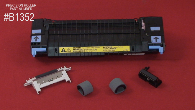
These instructions will help explain maintenance kit installation steps for an HP Color Laserjet 3600 and similar models. Maintenance Kit (PR# B1352)
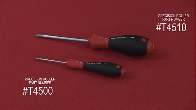
Tools Required
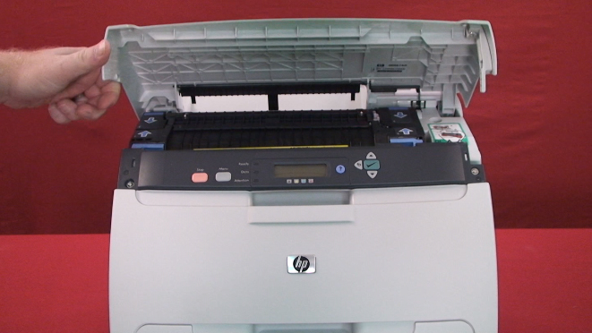
Before Install Caution if you have been using the printer the fuser section will be hot! Please allow the fuser to cool for at least 30 minutes before removing it. Remove the Fuser
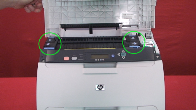
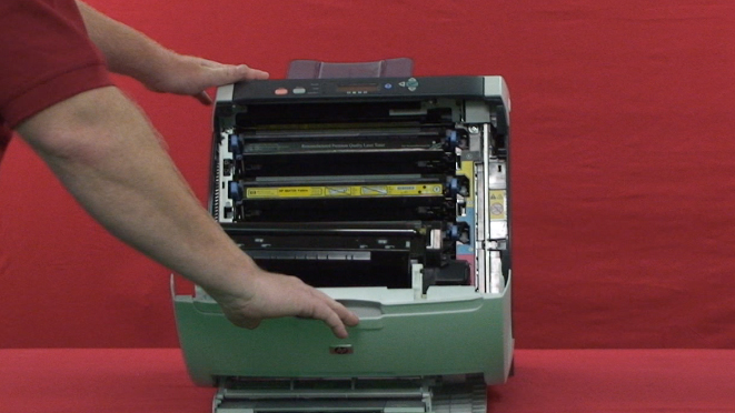
Locate the fuser and pinch the two blue fuser tabs in the direction of the blue arrows. While pinching the tabs, slightly rotate the fuser away from you and lift the fuser up and out of the printer.
Install the Fuser Removing the Transfer Belt Assembly
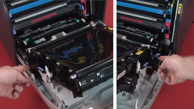
The transfer belt assembly has two small blue tabs on each side keeping the transfer belt assembly locked into place.
Pinch the small blue tabs simultaneously to unlock and release the transfer belt assembly.
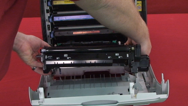
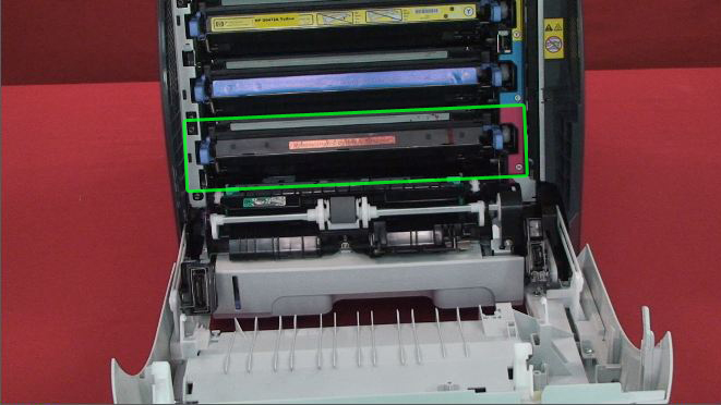
Once the transfer belt assembly is unlocked remove it away from the printer. Removing the Manual Feed Pickup Roller
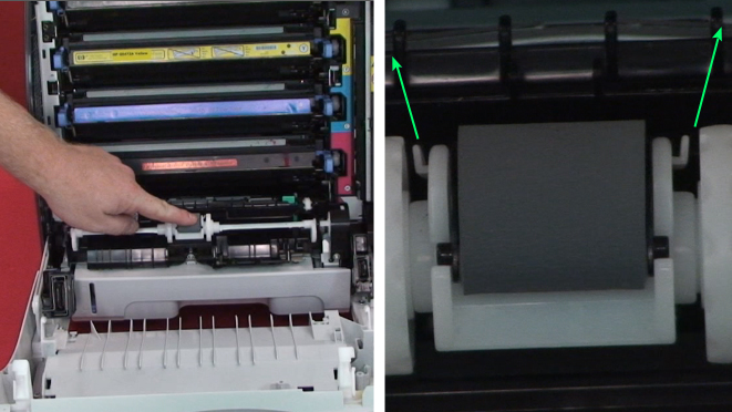
Pry the small white tabs of the holder apart and the roller will pop out freely then remove it from the printer. Removing the Separation Pad
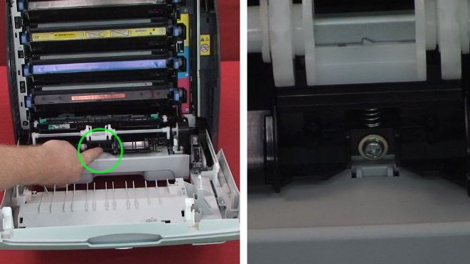
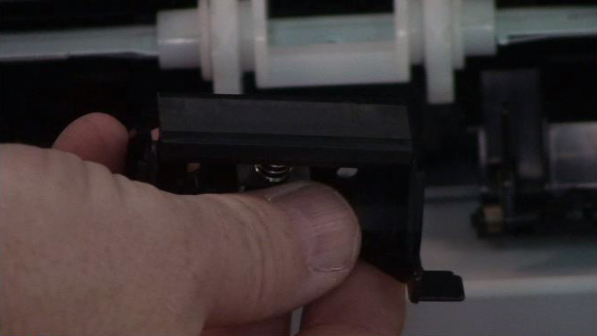
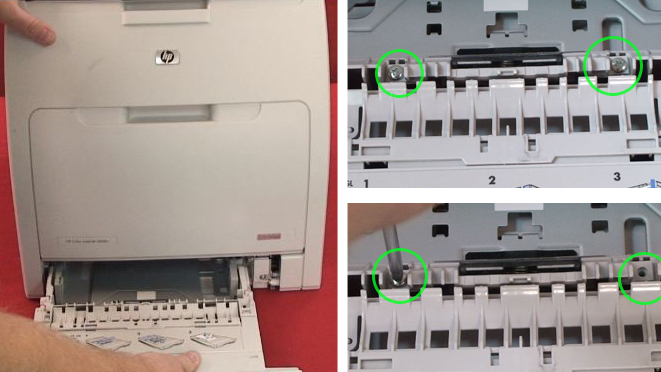
Once the screw is removed then slide the separation pad assembly out of the printer.
Installing the Separation Pad Installing the Manual Feed Pickup Roller Removing the Cassette Pickup Roller
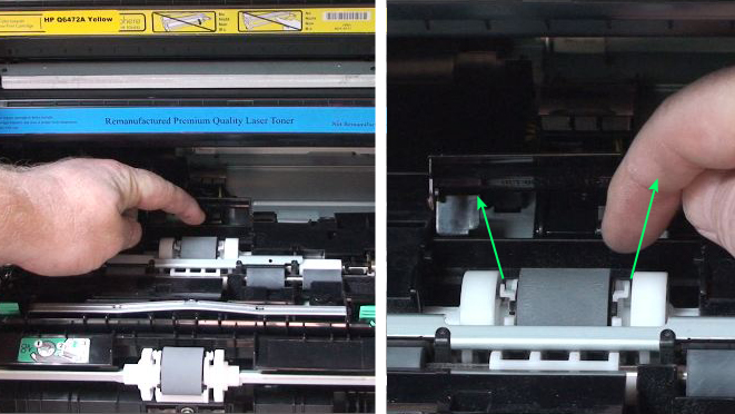
Next lift the hinged small black plastic cover to access the cassette pickup roller. Release the roller by sliding apart the two latches located on each side at the top of the pickup roller simultaneously until the roller pops out free.
Installing the Cassette Pickup Roller Installing the Transfer Belt Assembly Replacing the separation pad
Installing the separation pad Plug the power cord into the printer and turn the printer on.
|
Orders placed by 4:00 PM MST get
SAME DAY SHIPPING
for items listed as in stock
©2003-2025 Precision Roller. • 2102 West Quail Avenue, Suite 1 • Phoenix, AZ 85027 • (800) 323-9523 / (623) 581-3330 • M-F 7:30am - 5:00pm MST (noDST)
Individual brands are copyrighted by their respective owners. Precision Roller is in no way affiliated, sponsored or endorsed by these copyright owners or their affiliates or dealers
This website uses a secure server to encrypt all sensitive information.
Questions? Concerns? Send us a note at webmaster@precisionroller.com
This website uses a secure server to encrypt all sensitive information.
Questions? Concerns? Send us a note at webmaster@precisionroller.com


 Ricoh Black Extra High Yield Toner Cartridge
