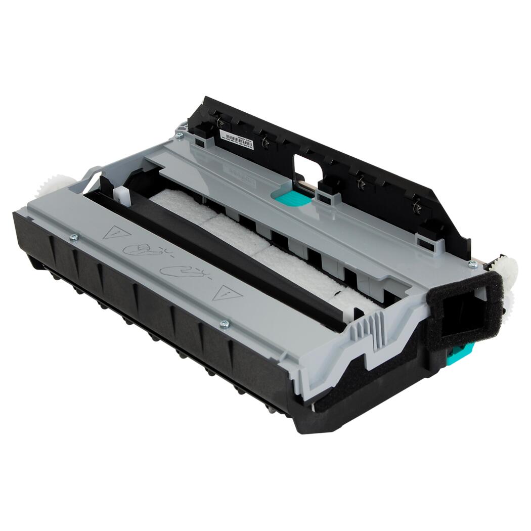
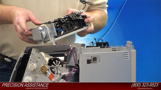
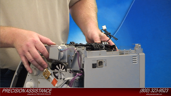
Contact
Visit Precision Roller on Facebook
Follow Precision Roller on Twitter Watch Precision Roller on YouTube Follow Precision Roller on Pinterest
Save 10% and Sign Up for Coupons on Printer Ink, Toner, and Supplies

HP Color LaserJet 2600N Maintenance Kit Instructions

Originally written for: HP Color LaserJet 2600n
Also applies to: HP Color LaserJet 1600
  • Date:

    Oct 11, 2013

These instructions will help explain maintenance kit installation steps for an HP Color LaserJet 2600N and similar models.

Before Installation:
Turn the power off and unplug the power cord from the printer. Caution if you have been using the printer the fuser section will be hot! Please allow the fuser to cool for at least 30 minutes before removing it.

Removing the Separation Pad:
Remove tray 2 from the printer by pulling it straight out of the printer.


Remove the two screws that attach the separation pad with a Phillips screw driver and set them aside.

Remove the separation pad assembly by pulling it straight out of the printer.

Installing the Separation Pad:
Install the new separation pad assembly by sliding the empty slot that you removed it from in tray 2.

Reinstall the two screws that attach the separation pad with a Phillips screw driver and tighten them.

Reinstall tray 2 into the printer by sliding it in and confirming it locks into place.

Removing the Pickup Roller:
Using the front handle open the front door of the printer.

Remove all four of the toner cartridges by grasping the blue handles of the toner cartridges on each side and pull them straight out of the printer.


Remove two screws that connects the pre-transfer guide.

Remove the pre-transfer guide.

Use a small screwdriver to pull back on the tabs of the paper pickup roller.


Rotating it towards the back, remove the paper pickup roller.

Installing the Pickup Roller:
Install the new paper pickup roller by sliding it in towards the back and rotate it towards the front until it will snap into place.


Reinstall the pre-transfer guide and then replace the two screws that hold the pre-transfer guide into place.


Install the toner cartridges and close the front door.


Removing the Fuser:
Remove the paper delivery tray assembly from the printer.


Remove the two screws from the right cover assembly.

Remove the right cover assembly and carefully disengage the catches.


Unplug the control panel cable.

Insert a screwdriver to loosen the release tab on each side of the upper face cover.


Remove the upper face cover.


Remove the four screws from the upper cover.

Lift up and remove the face-down cover.


Remove the output tray by releasing the tabs.


Unplug the harness from the fuser motor.

Open the two clips and remove one clip to remove the fuser connector.


Remove the clip from the board by pulling it up and out from the printer.

Unplug the two 3-pin optical encoder wires.

Unplug the red high-voltage bias wire.

Remove the thermistor wire.

Remove the cables from the wiring harness.

Remove three screws from the fuser chassis.


Gently rocking if necessary, roll the fuser forward to remove.

Installing the fuser:
Align the fuser tabs with their respective holes gently install the fuser.


Install the three screws to the fuser chassis.


Install the cables to the wiring harness.


Install the thermistor wire.

Plug in the red high voltage bias wire.

Plug in the two 3-pin optical encoder wires.

Close the two clips.

Plug in the harness from the fuser motor.

Install the output tray.

Install the face down cover.


Install the four screws to the upper cover.

Install the upper face cover.


Plugin the control panel cable.

Install the right cover assembly.


Install the two screws from the right cover assembly.

Install the paper delivery tray assembly to the printer.


  • Publisher: Precision Roller