Contents
- Introduction
- Replacing or cleaning the pickup roller
- Replacing or cleaning the separation pad
- Replacing the transfer roller
- Replacing the fuser assembly
- Ordering supplies and accessories
Introduction
This document explains how to install and maintain the consumables for the HP LaserJet 1150 and 1300 series printers, which consist of the pickup roller, the printer separation pad, the transfer roller and the fuser assembly.
These four regular maintenance items are available in the HP Laserjet 1150 Maintenance Kit (PN V7570).
This kit includes:
Replacing or cleaning the pickup roller
If the printer frequently jams when trying to pull in the paper, or tries to pull in more than one sheet at a time, it may be necessary to change or clean the pickup roller.
NOTE: Failure to complete these procedures when needed could cause damage to the printer.
Replacing the pickup roller
Use the following steps to replace the pickup roller:
- Unplug the power cord from the printer, and allow the printer to cool.
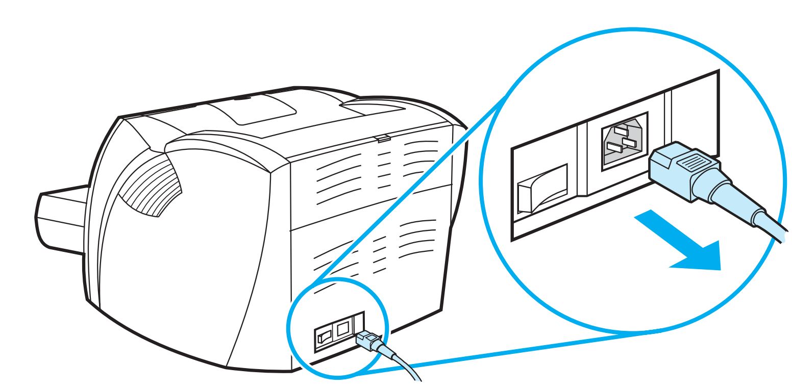
Power cord unplugged
- Open the print cartridge door, and remove the print cartridge.
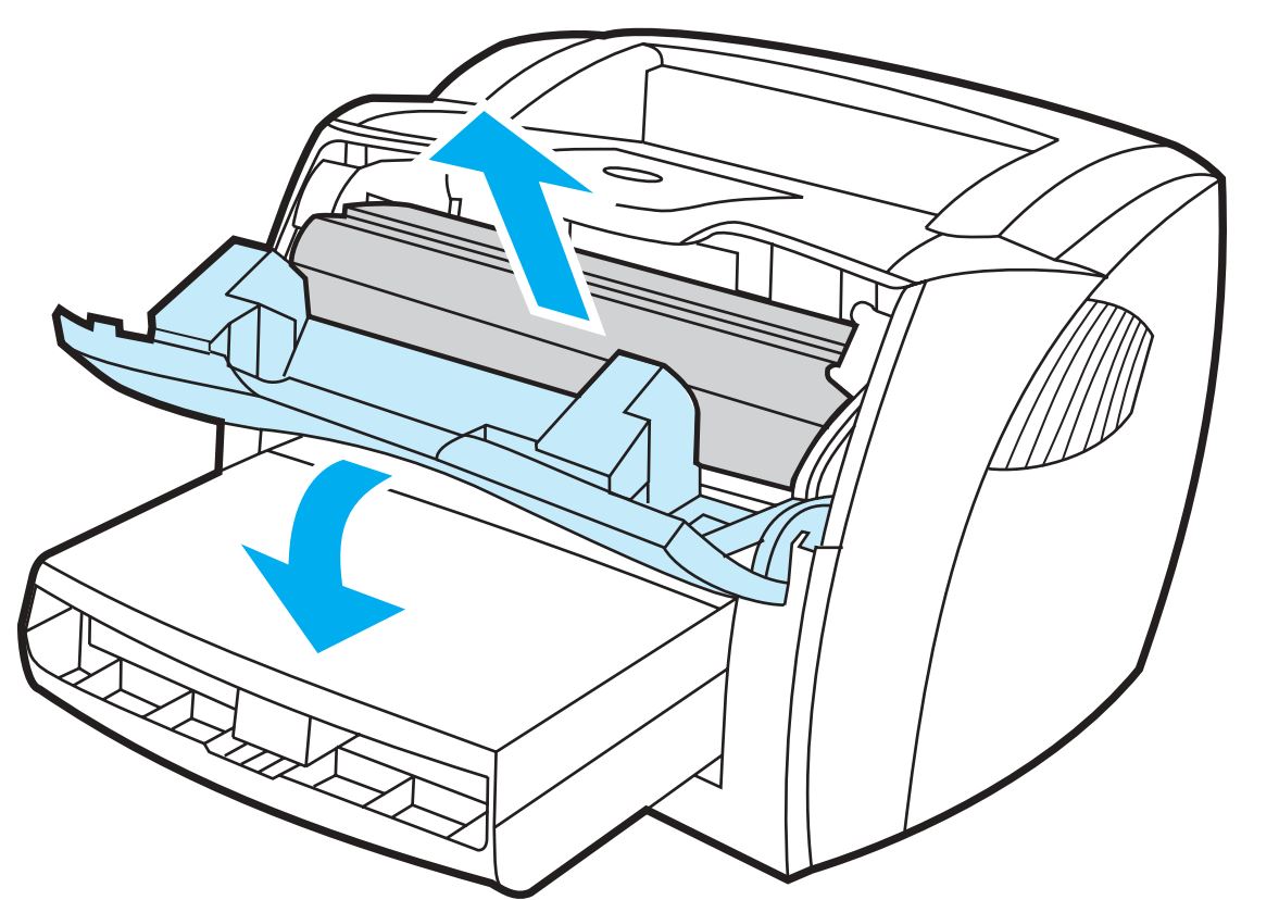
Print cartridge door opened and print cartridge removed
- Find the pickup roller.
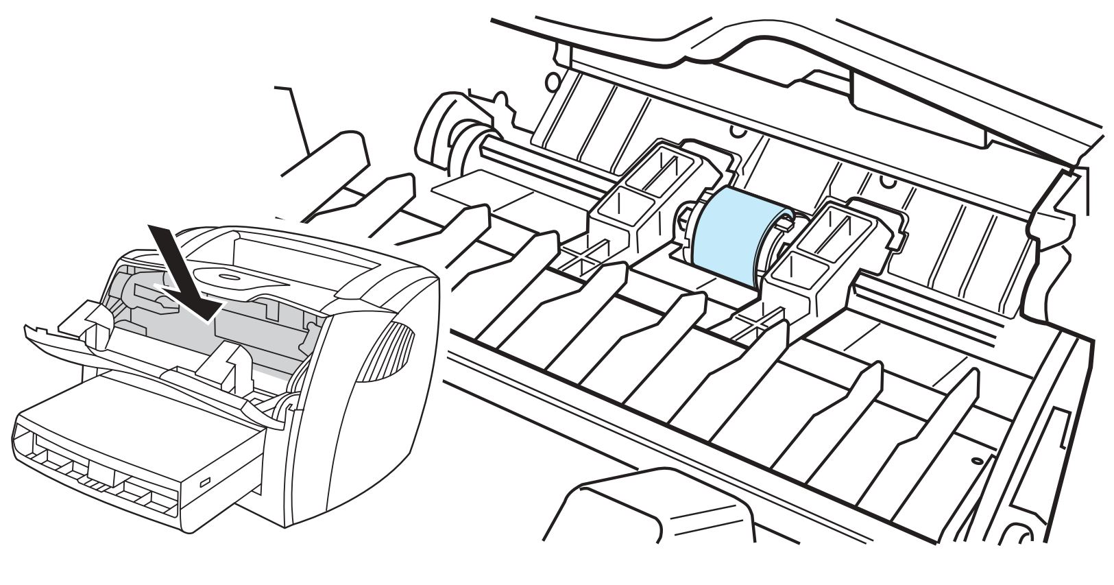
Location of pickup roller
- Release the small tabs on each side of the pickup roller by pushing them away from the roller, and rotate the pickup roller toward the front.
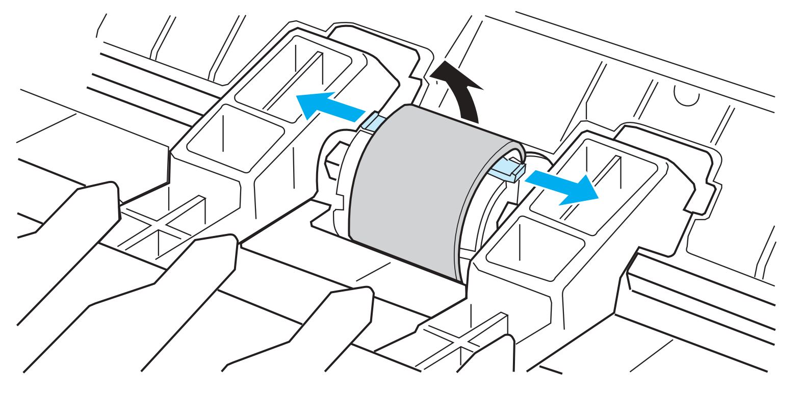
Tabs released and pickup roller rotated toward front
CAUTION: The tabs are fragile. Be careful not to break them.
- Gently pull the pickup roller up and out.
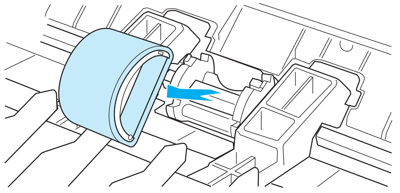
Pickup roller removed
- Position the new or cleaned part in the slot of the previous pickup roller. (Click here to go to "Cleaning the pickup roller" for instructions about cleaning.)
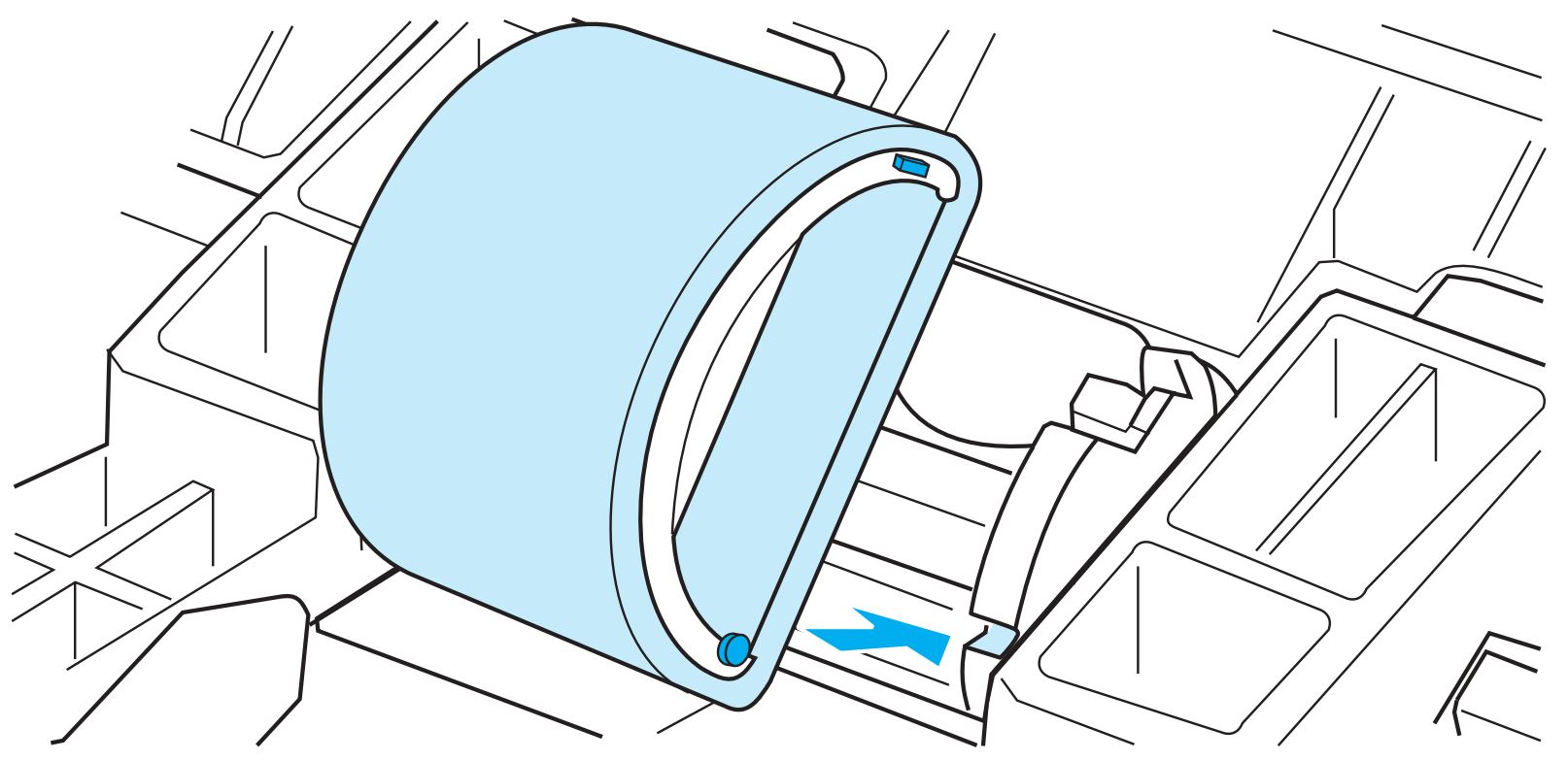
Pickup roller positioned in place
NOTE: Circular and rectangular pegs on each side prevent the pickup roller from being incorrectly positioned.
- Rotate the top of the new pickup roller into position until the tabs on each side of the roller snap into place.
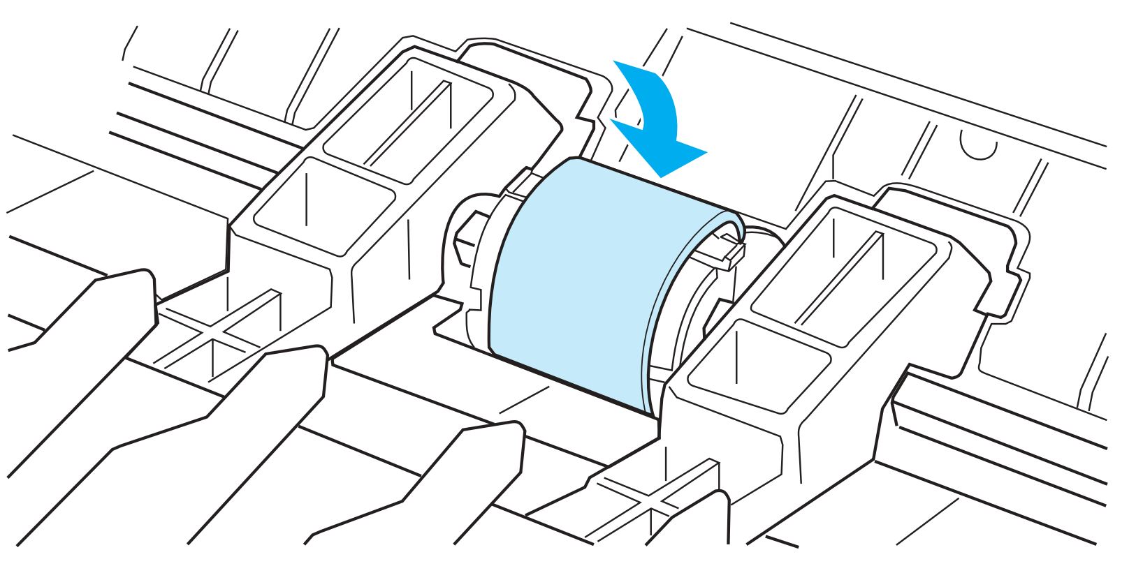
Pickup roller snapped into place
CAUTION: The tabs are fragile. Be careful not to break them.
- Reinstall the print cartridge, and close the print cartridge door.
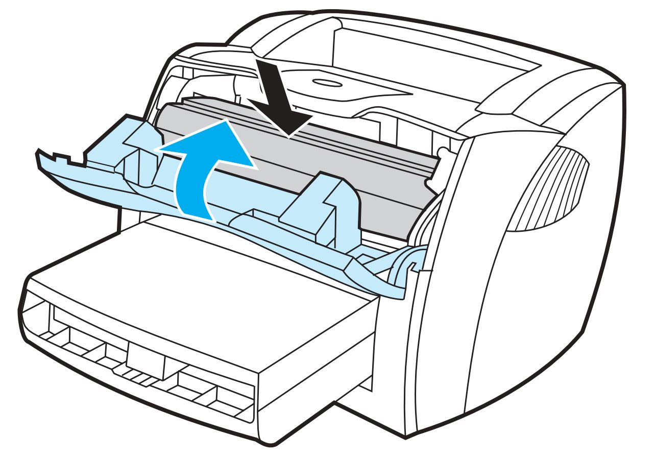
Print cartridge reinstalled
- Plug the power cord back into the printer to turn the printer on.
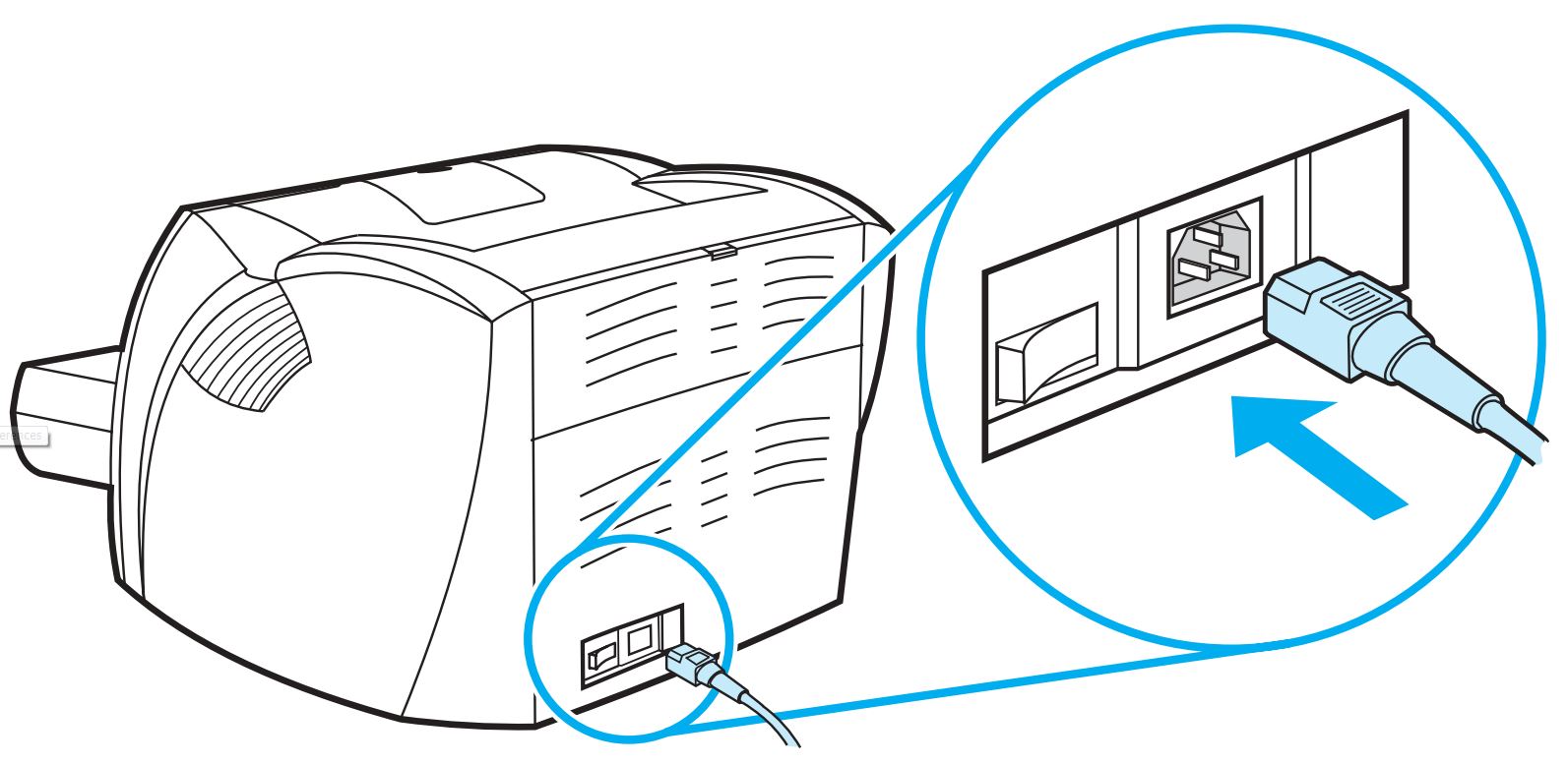
Power cord plugged in
Cleaning the pickup roller
Use the following steps to clean the pickup roller rather than replace it.
- Remove the pickup roller as described in Steps 1 through 5 for changing the pickup roller. (Click here to go to the steps for changing the pickup roller.)
- Dab a lint-free cloth in clean water, and scrub the roller.
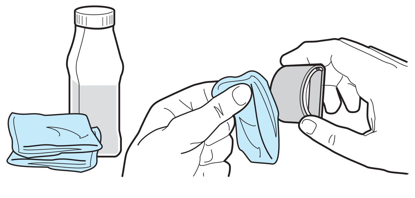
Roller scrubbed with clean water
- Using a dry, lint-free cloth, wipe the pickup roller to remove loosened dirt.
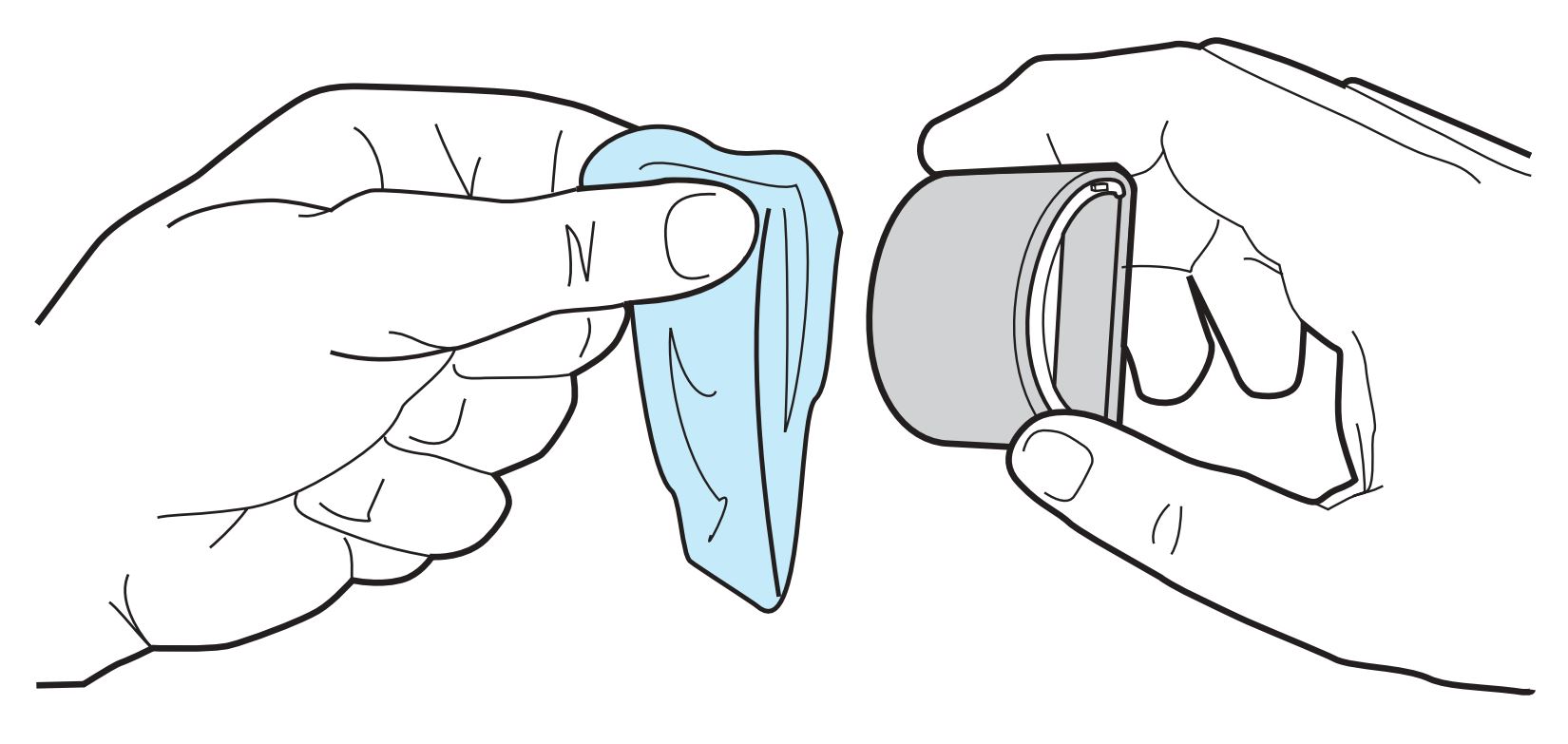
Roller wiped with lint-free cloth
- Allow the pickup roller to dry completely before reinstalling it in the printer. Reinstall the pickup roller as described in Steps 6 through 9 for changing the pickup roller. (Click here to go to the steps for reinstalling the pickup roller.)
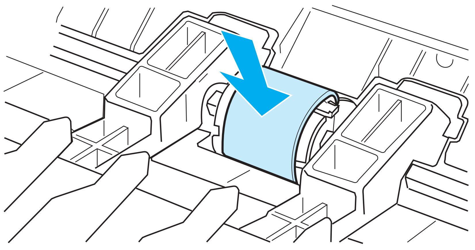
Pickup roller snapped into place
Replacing or cleaning the separation pad
If the input tray feeds more than one page at a time, it might be necessary to change the printer separation pad. Recurring feed problems may indicate that the printer separation pad is worn.
CAUTION: During this procedure, be careful not to break the tabs on the separation pad.
Replacing the printer separation pad
Use the following steps to replace the printer separation pad.
- Unplug the power cord from the printer, and allow the printer to cool.

Power cord unplugged
- Remove the input trays.
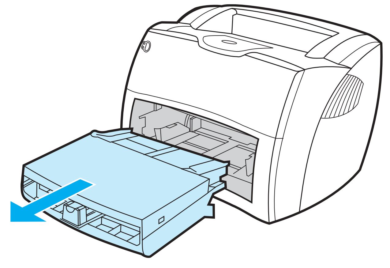
Input trays removed
- Find the blue separation pad. (For the HP LaserJet 1300 series, it might be necessary to push down the media lift plate to see the separation pad.)
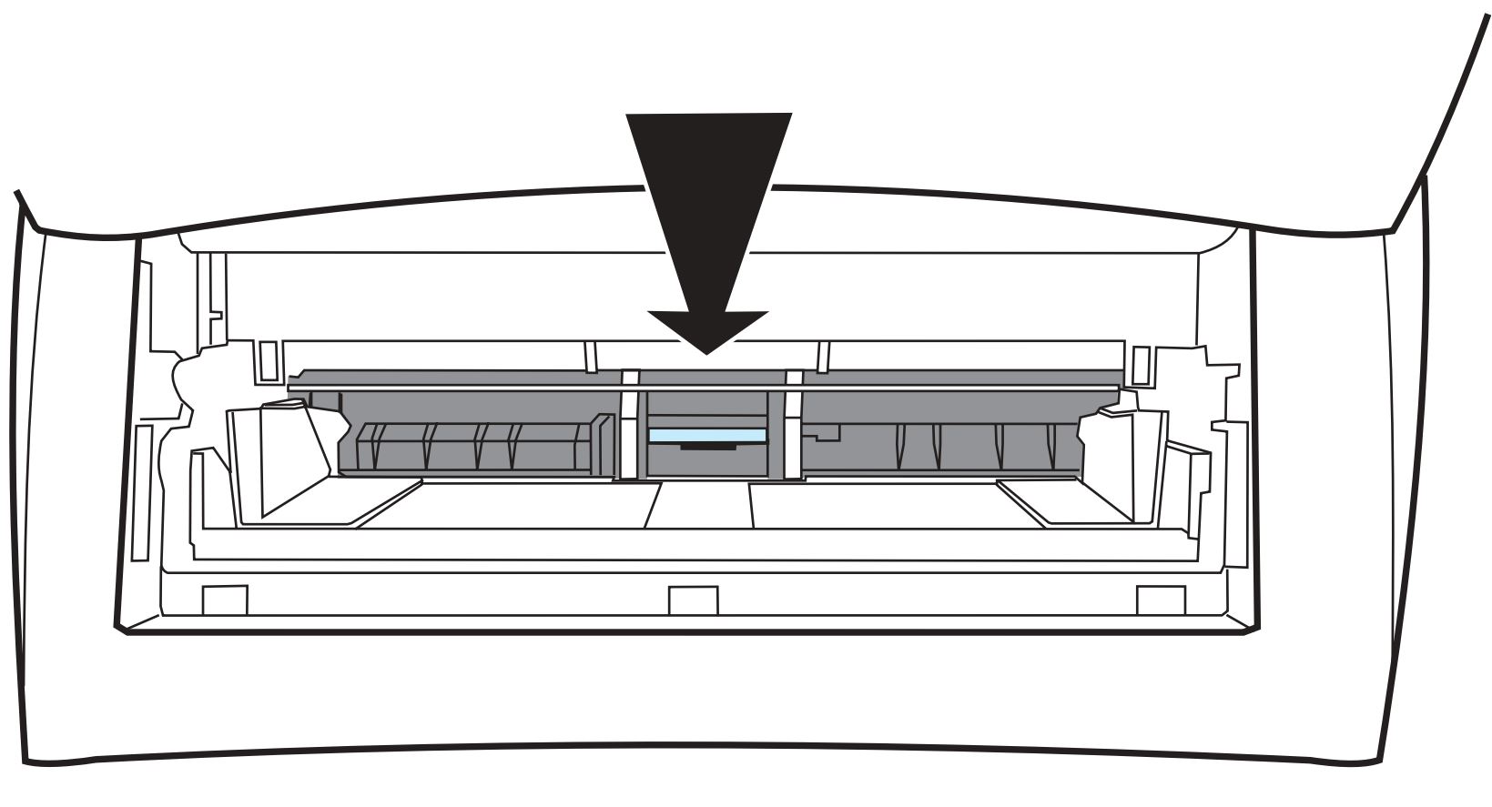
Blue separation pad
- To pry the separation pad up from the spring-loaded base, insert a flat-edged screwdriver in the slot under the separation pad and twist until the tabs are free.
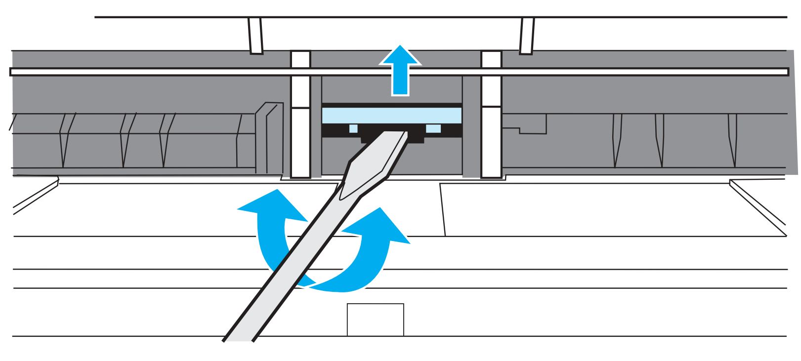
Separation pad freed from spring-loaded base
CAUTION: The tabs are fragile. Be careful not to break them.
- Reach in through the opening, push the spring-loaded base down with one hand, and pull the separation pad up with the other hand.
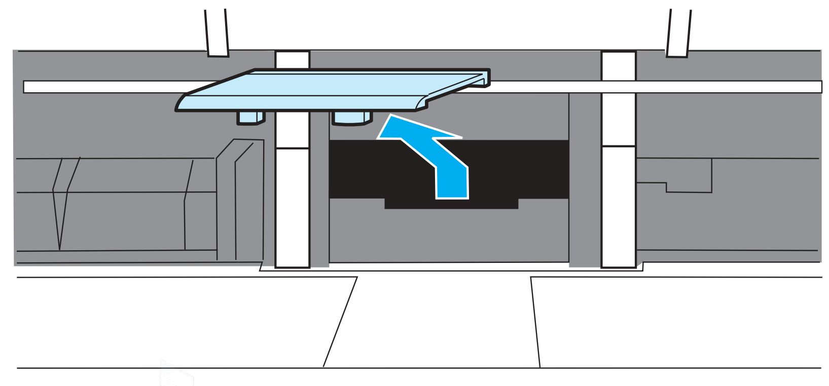
Separation pad removed
- With one hand, position the new separation pad in the slot of the previous separation pad (callout A). With the other hand, reach through the input tray opening, and push the spring-loaded base down (callout B).
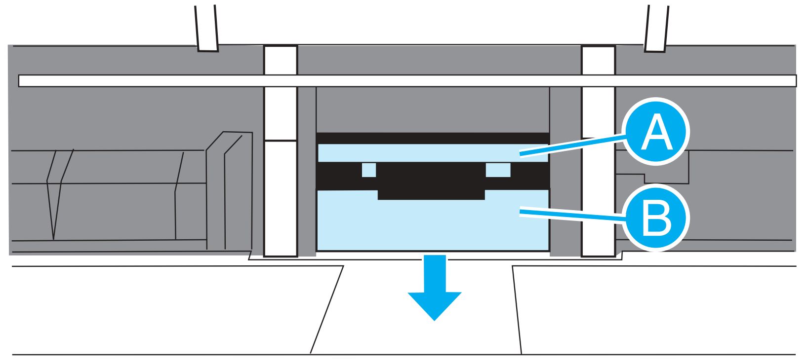
New separation pad positioned in place
A - New separation pad positioned in slot
B - Spring loaded base
NOTE: The tab on the right is larger to help in positioning it correctly.
- Snap both sides of the separation pad firmly into place.
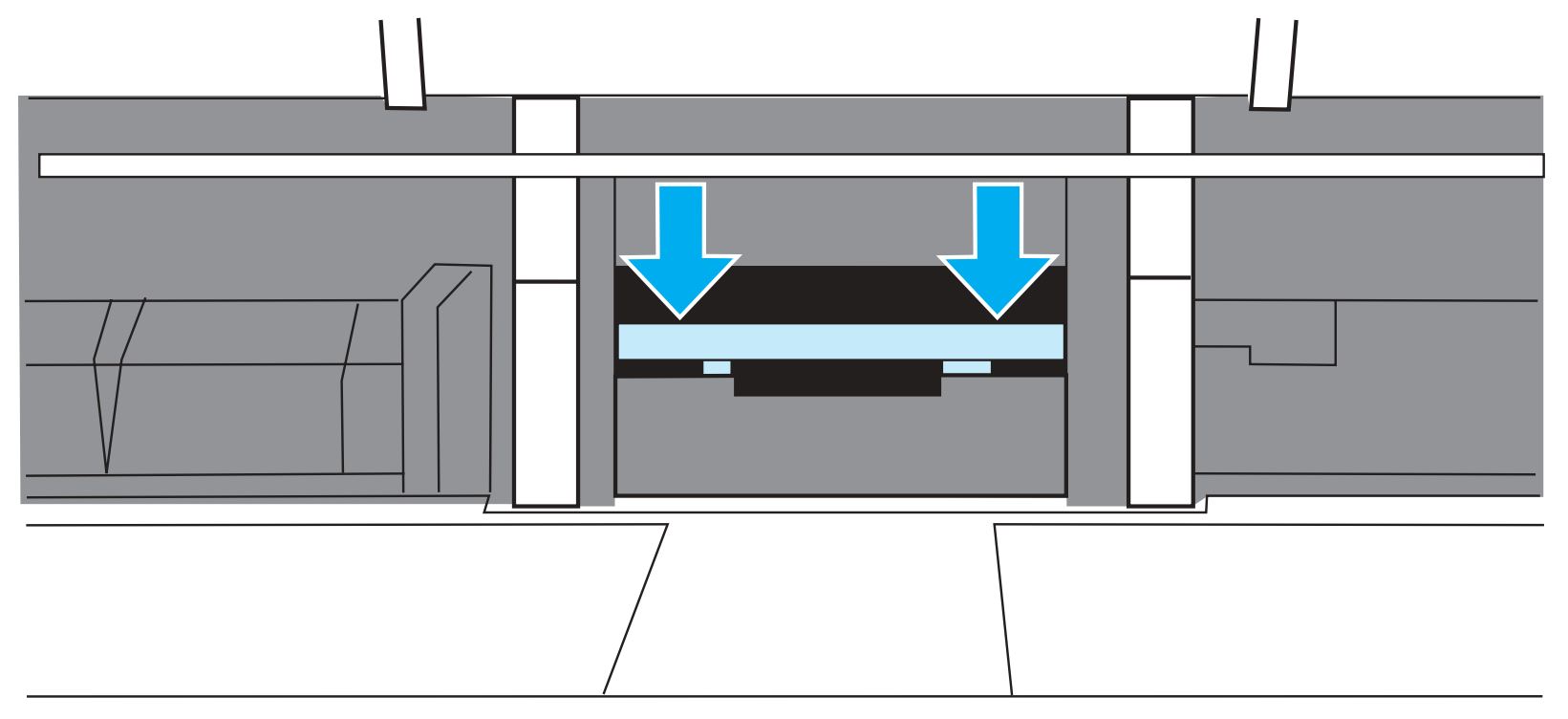
Separation pad snapped into place
CAUTION: Make sure that the separation pad is straight and that there is no space between the separation pad and the spring-loaded base. If the separation pad is not straight or there is a space on one side, remove the separation pad, make sure that the larger tab is on the right, reinsert the separation pad, and snap both sides into place.
- Reinsert the pickup roller, print cartridge, and input trays. Plug the printer in to turn it back on.

Printer plugged in
Replacing the transfer roller
Removing the transfer roller
- Open the print cartridge door and remove the print cartridge. You may feel slight resistance when opening the print cartridge door.
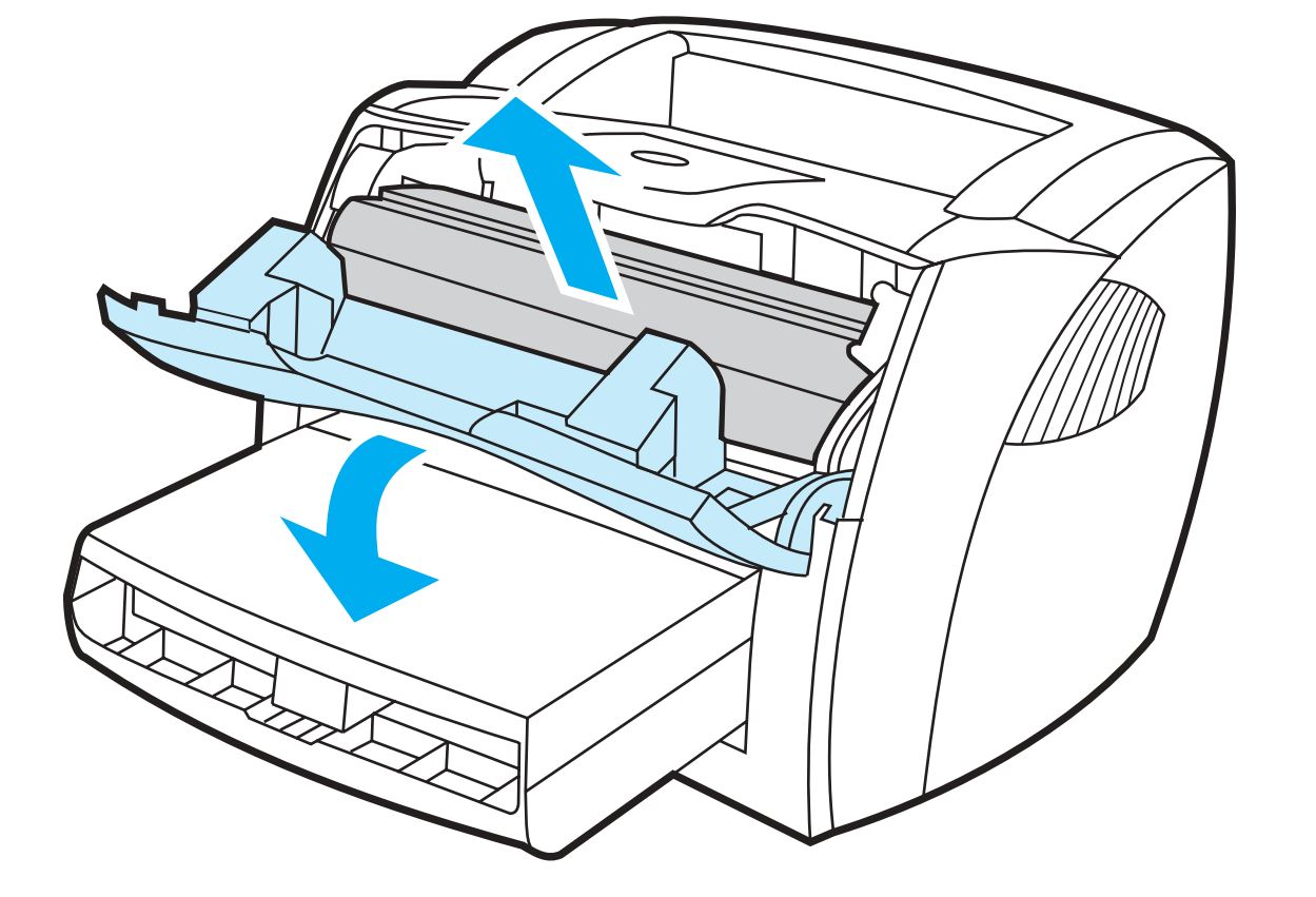
Removing print cartridge
- Use a pair of needle nose pliers (PR# T1420) to gently squeeze the two small tabs on the transfer roller. Be careful not to touch the black sponge portion of the transfer roller.
- Lift the transfer roller up, slide it to the right, and carefully lift it out of the printer. Use extra caution not to misplace the small grounding spring that is beneath the right side of the transfer roller.
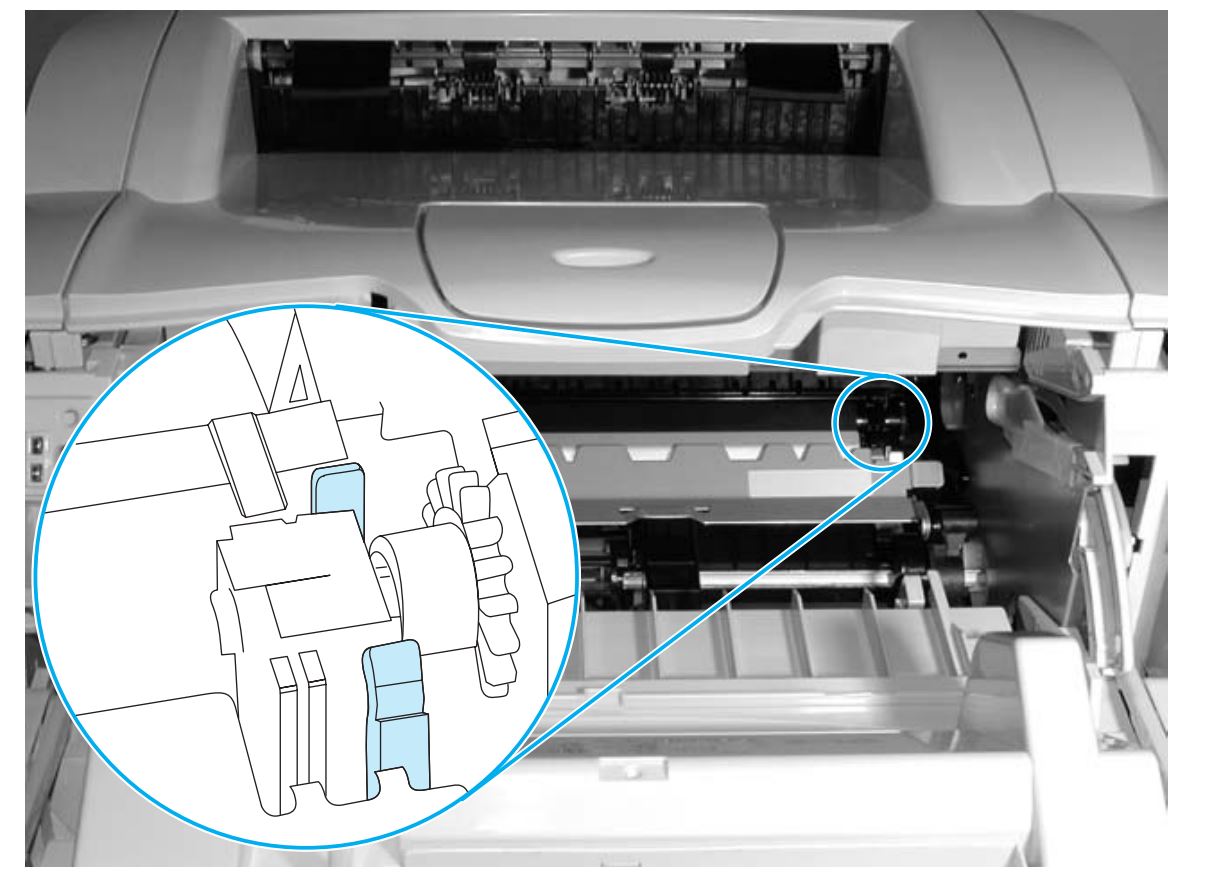
Removing transfer roller
Replacing the fuser assembly
Removing the fuser assembly
- Remove the left side cover by pulling out on the notch (callout 1) on the rear side of the cover. Rotate the cover away from the printer.
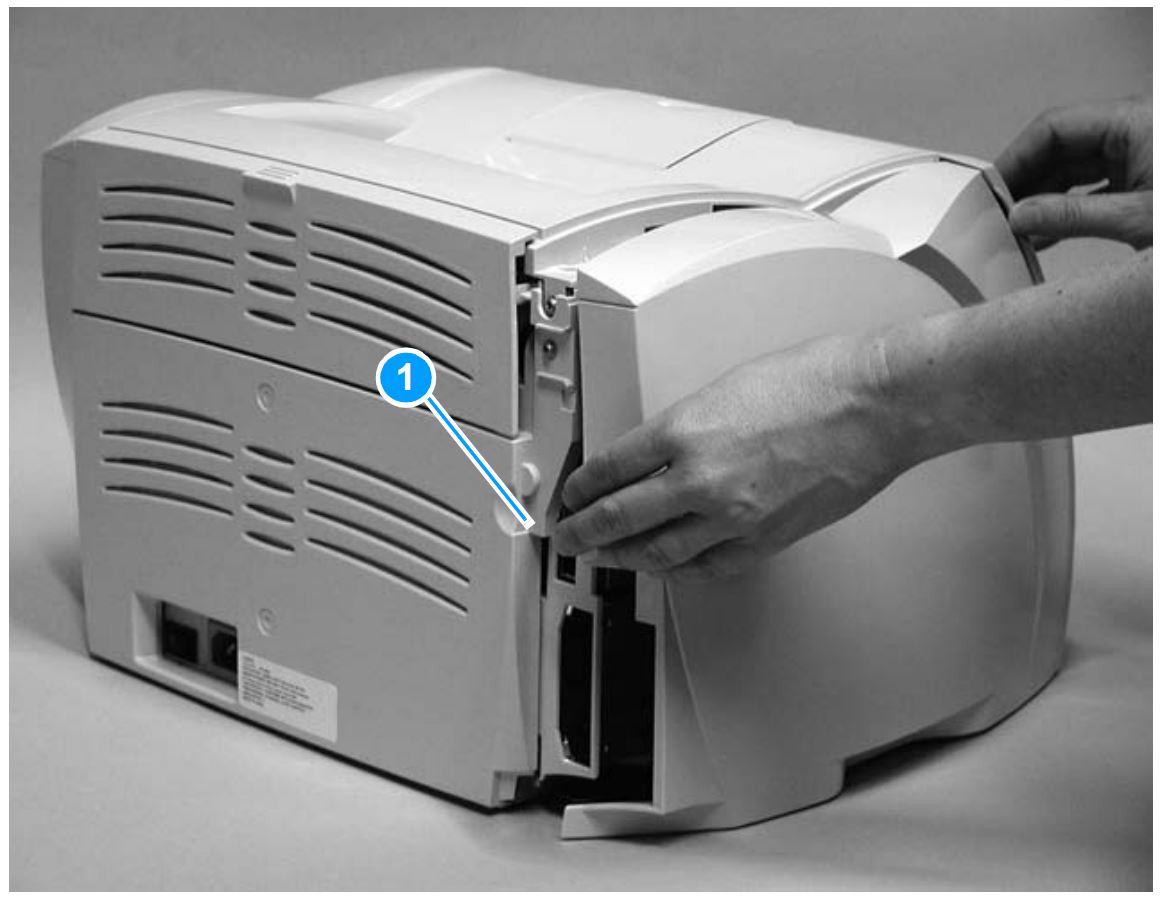
Removal of left side cover
- To remove the back cover, open the straight-through output door and remove the two screws (as shown below) from the rear side of the printer. Press down and hold the two release levers in order to fully remove the cover from the machine.
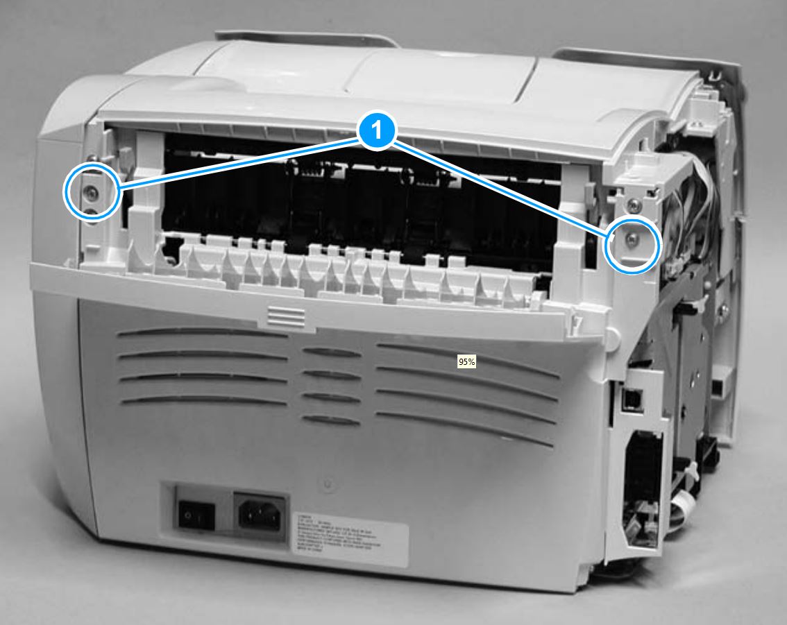
Removal of back cover
- To remove the right side cover, remove one screw (callout 1) on the rear side of the printer. Lift the right side of the printer and release the tab (as shown in callout 2) on the bottom side of the cover. While pressing the release tab, gently rotate the cover away from the printer.
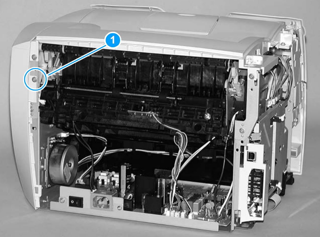
Removal of right side cover
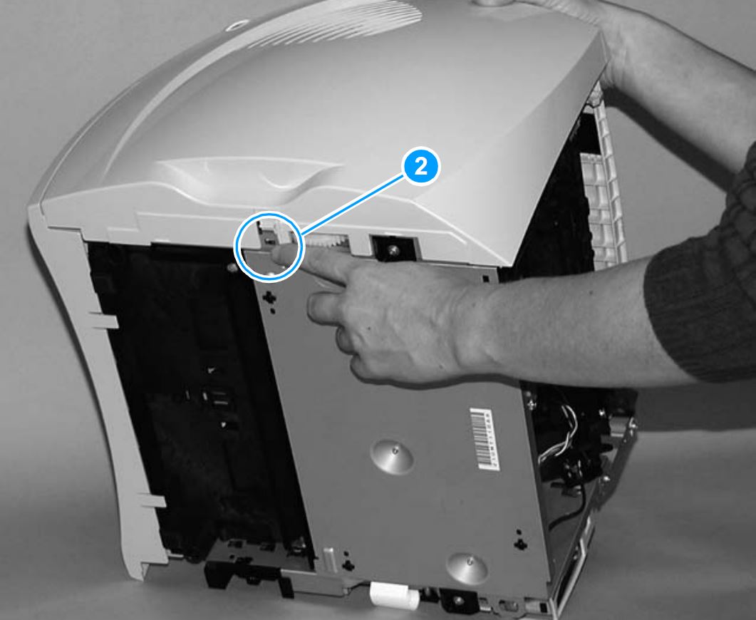
Removal of right side cover

Removal of right side cover
- To remove the top cover, loosen two screws (callout 1) on the rear side of the printer and the two screws (callout 2) on the top of the printer. Gently lift the cover off of the printer.
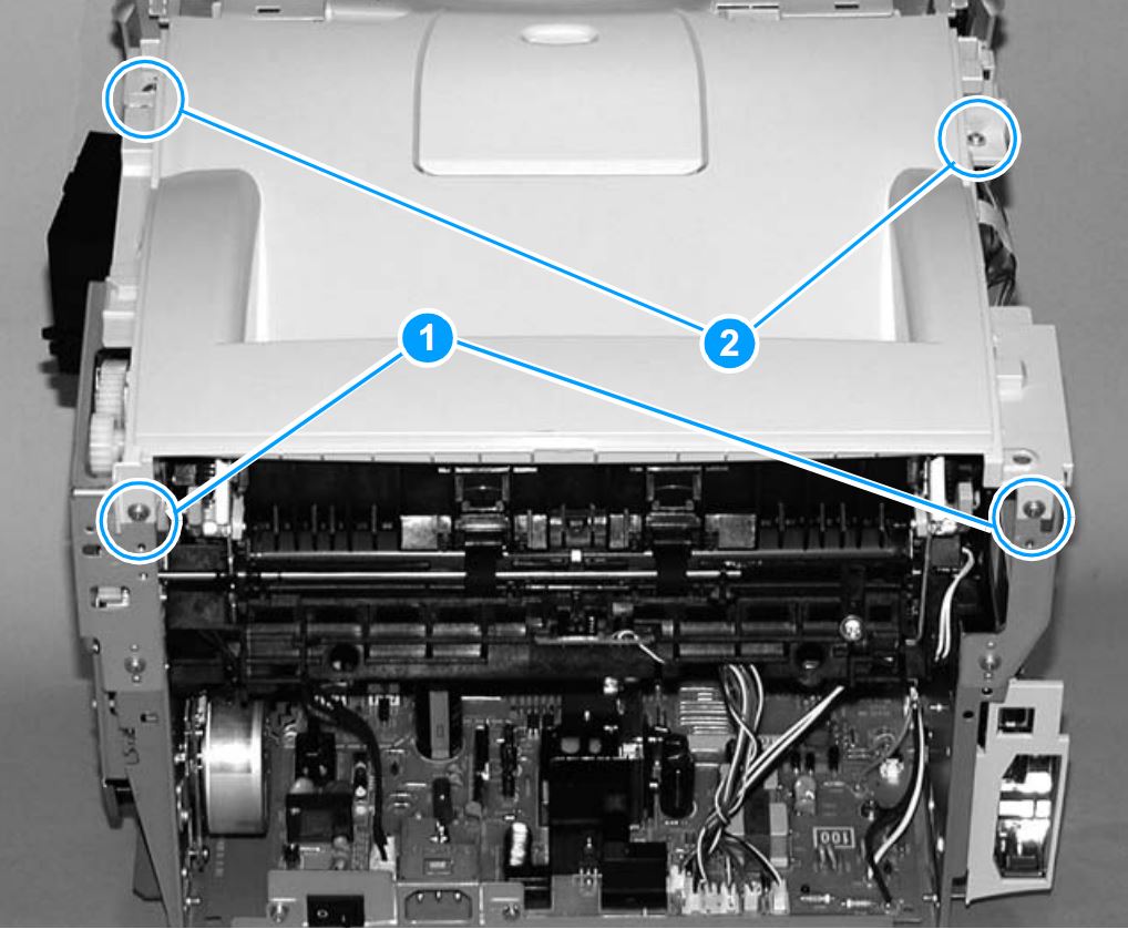
Removal of top cover
- Remove the right side bracket holding the fuser assembly in place by removing three screws (callouts 1, 2 and 3) from the right fuser plate. Keep in mind that the third screw is located behind the large gear on the right fuser plate and can be accessed through the holes in the 69T gear.
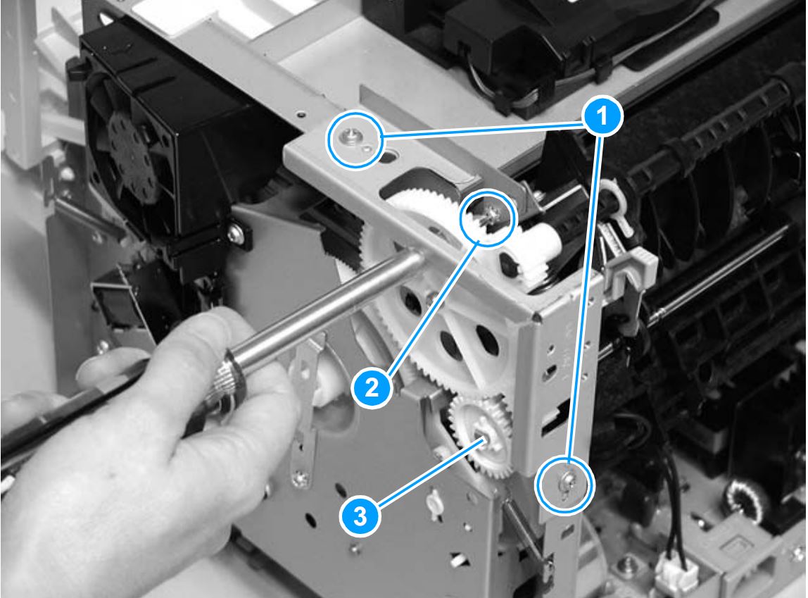
Removal of right bracket
- Remove the left side bracket holding the fuser assembly in place by removing three screws (callout 4) from the left fuser plate.
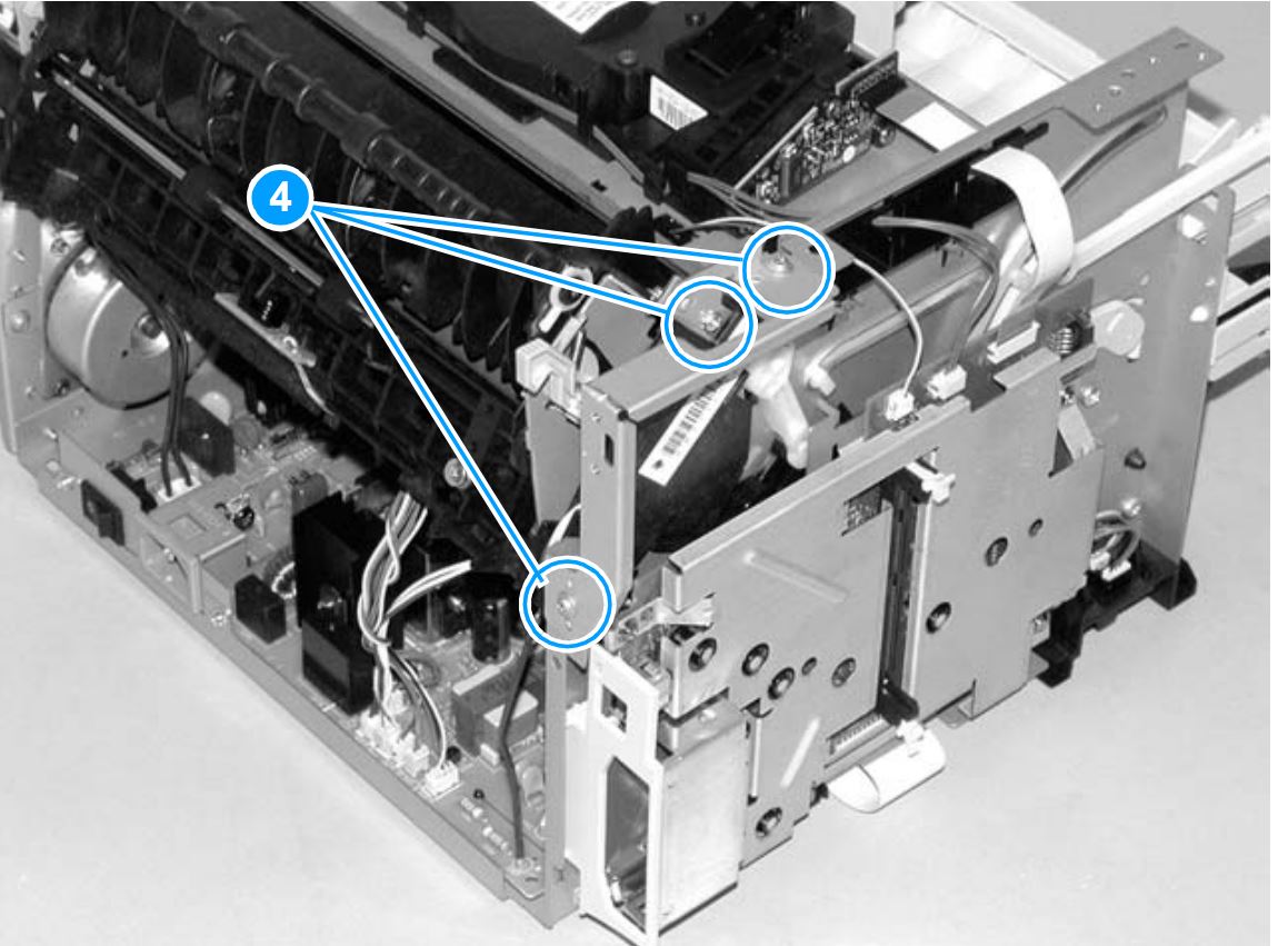
Removal of left bracket
- Remove the two screws as shown in callout 5; each screw is located on the side of the printer.
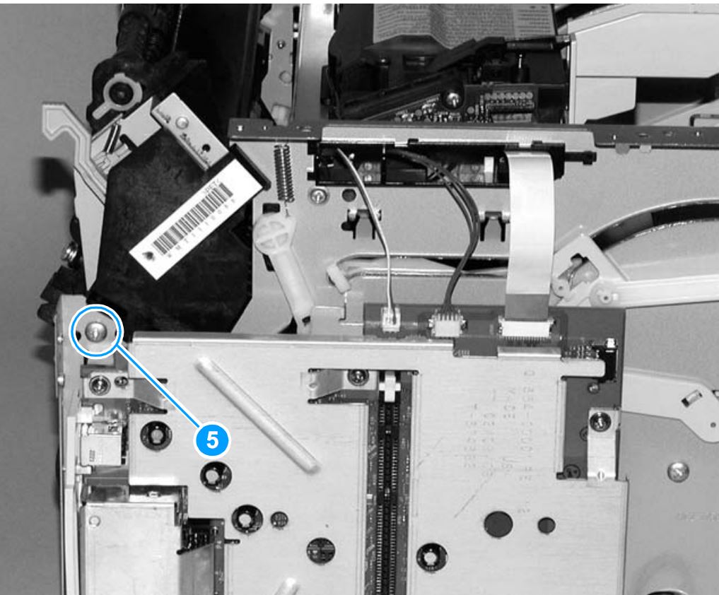
Removal of additional screws
- Disconnect the following connectors: the fuser cable connector (callout 6) by pressing and releasing the tab on the back of the connector, the black and white fuser cable connector (callout 7) from the ECU, and the spade connector (callout 8) that is located at the very rear of the printer. Remove one screw (callout 9) from the paper delivery sensor, and lift the paper delivery sensor out of the printer. Pull outward on both sides of the printer frame in order to release the fuser. Carefully lift the fuser assembly out of the printer.
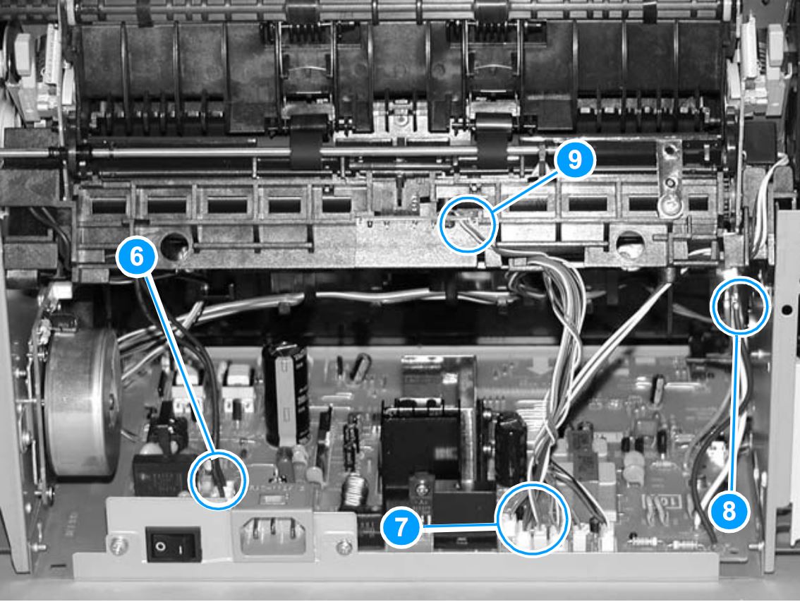
Disconnecting connectors
Reinstalling the fuser assembly
- The 29T pressure roller gear (PR# J6235) is not part of the replacement fuser assembly. You can transfer the 29T pressure roller gear from the old fuser unit to the new fuser unit by releasing the tab in the center of the gear. Use extra caution not to damage the tab. Remove the large gear from the end of the fuser assembly, return the fuser assembly to the chassis, and replace the large gear.
- Perform all steps listed above in reverse order to reinstall the fuser assembly.
Ordering supplies and accessories
The following table lists common HP supplies and accessories.
|
Type
|
Item
|
Description or use
|
Part number
|
|---|
| Print cartridge for the HP LaserJet 1150 printer |
UltraPrecise print cartridge |
Replacement print cartridges for the HP LaserJet 1300 series printers. |
HP [Q2624X] |
| Print cartridges for the HP LaserJet 1300 series printer |
UltraPrecise print cartridges |
Replacement print cartridges for the HP LaserJet 1300 series printers. |
HP [Q2613A] (2,500-page cartridge)
HP [Q2613X] (4,000-page cartridge) |
| Maintenance Kit for the HP LaserJet 1150 series printer |
120 Volt Maintenance Kit |
Used to perform maintenance on the printer. |
HP [LJ-1300-KIT] |
Replacement parts
(included in kit) |
Media pickup roller |
Used to pick the media from the input tray and advance it through the printer. |
HP [RL1-0303-000] |
| Separation pad for the printer |
Used to keep multiple sheets from feeding through the printer path. |
HP [RF0-1014-000] |
| Transfer roller for the printer |
Used to transfer images onto paper. |
HP [RG9-1483-000] |
| Fuser assembly for the printer |
Unit that fuses the toner onto the paper being printed on. |
HP [RM1-0715-030] |


 HP Intermediate Transfer Belt (ITB) Assembly


