|
My Printers |
► |
Or browse by model:


|
Brother MFC-L8900CDW Fuser Replacement Instructions
Brother MFC-L8900CDW Fuser Replacement Instructions
Originally written for: Brother MFC-L8900CDW
Also applies to: Brother HL-L8260CDW, L8360CDW, L9310CDW, MFC-L8610CDW, L9570CDW
Installing a new fuser in a Brother MFC-L8900 and related models is a fairly easy procedure. Read on for the steps to change the fuser unit in these models.

Contents
- Introduction
- Recommended tools
- Step 1: Remove the fuser
- Step 2: Replace toner filter
- Step 3: Replace exit pinch rollers
- Step 4: Install the new fuser
- Step 5: Reset the fuser life counter
Introduction
The fuser in a Brother MFC-L8900CDW printer may need to be replaced for a number of reasons. There is a fuser lifetime copy counter set to show a message on the display recommending replacement once 200,000 pages have been printed through the fuser. It is also common to replace the fuser for lines appearing on the page. Occasionally, the Teflon surface of the heater roller will become scored by the separation pawls that are designed to separate the page from the surface of the roller. If one of these pawls begins to wear into the surface, toner will stick in this area and be deposited back on future pages in that area. Since the upper fuser roller is not available for individual purchase, the entire fuser will need to be replaced to fix the issue. Fortunately, the installation process is fairly straightforward.
Recommended tools
Step 1: Remove the fuser
- First, unplug the printer and let the printer cool down for at least 15 minutes.
Caution: The fuser might be hot. Wait at least 15 minutes before proceeding.
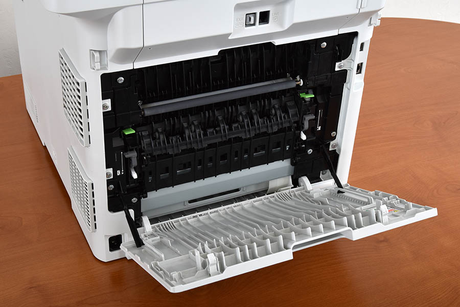
- Open the rear exit door of the printer.
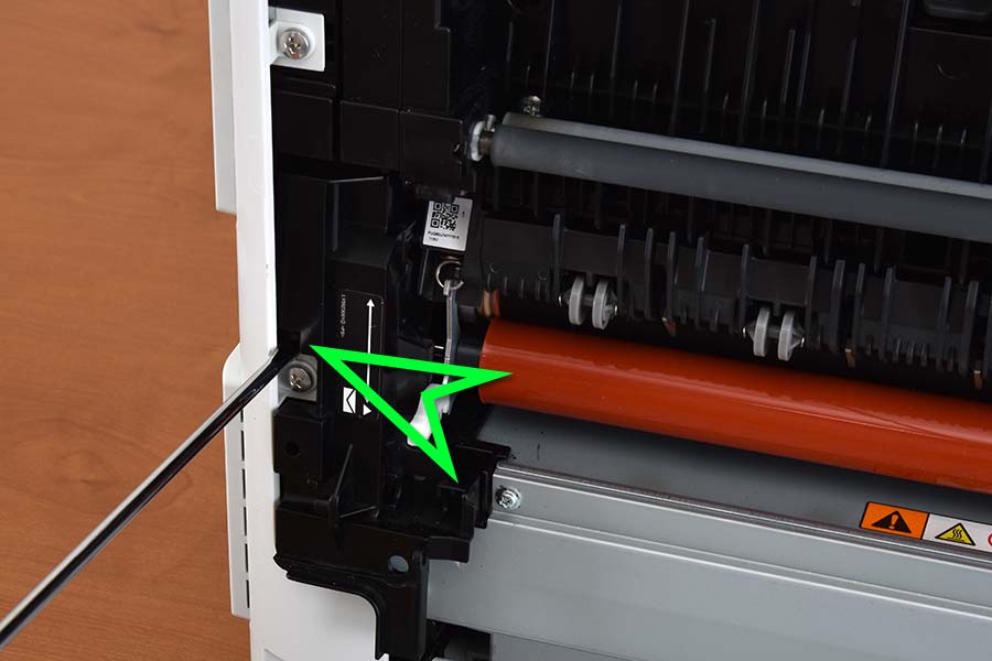
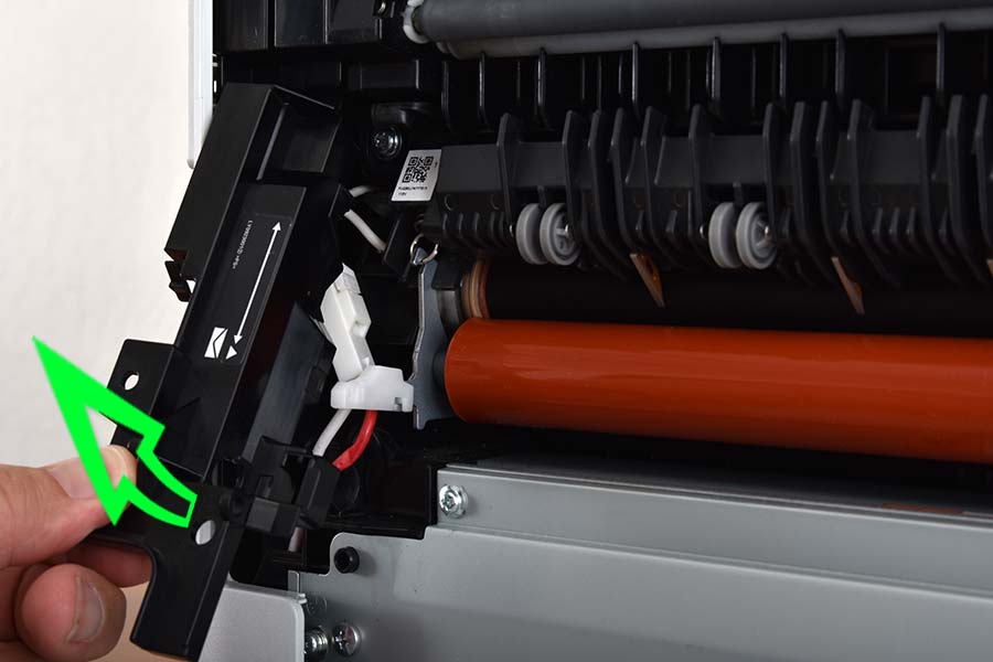
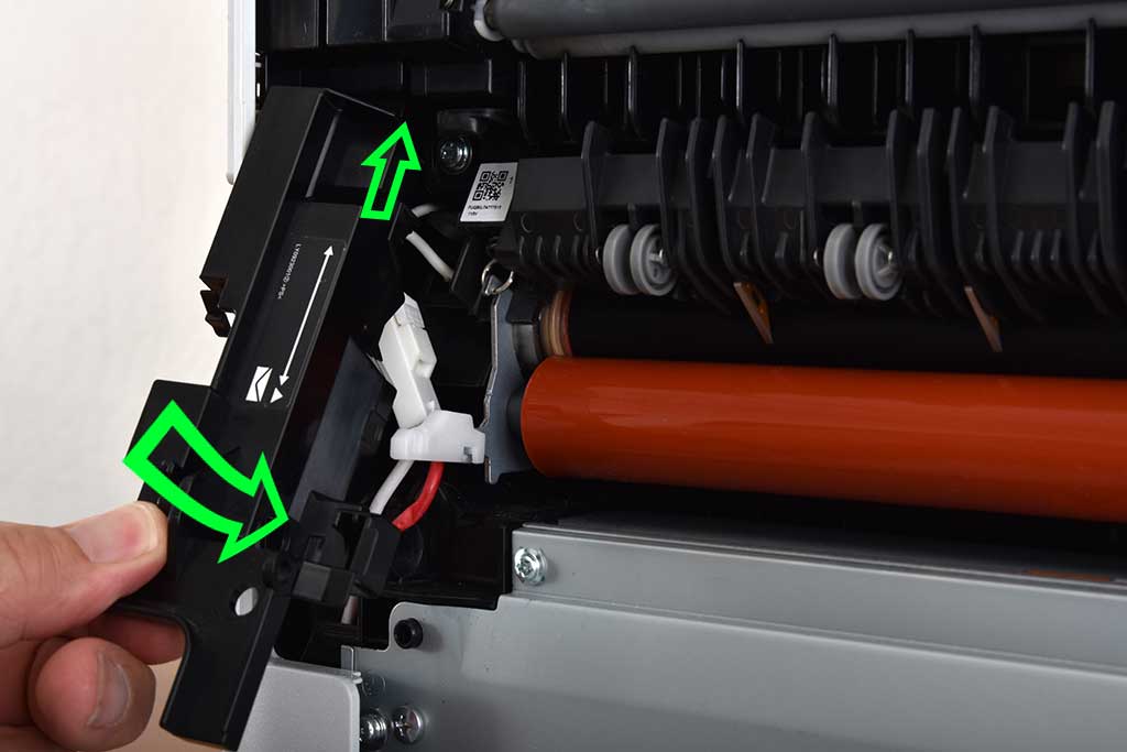
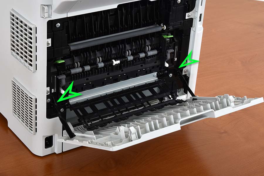
- De-latch the door support arms (as highlighted in the photos below) to allow the rear exit door of the printer to lay flat and provide additional working room to access the fuser unit.
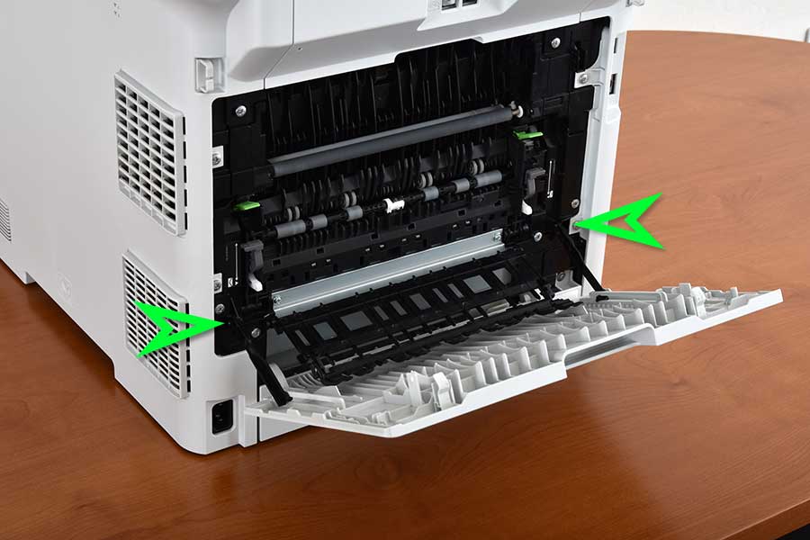 
Support arm locations
De-latch support arms by pulling upward
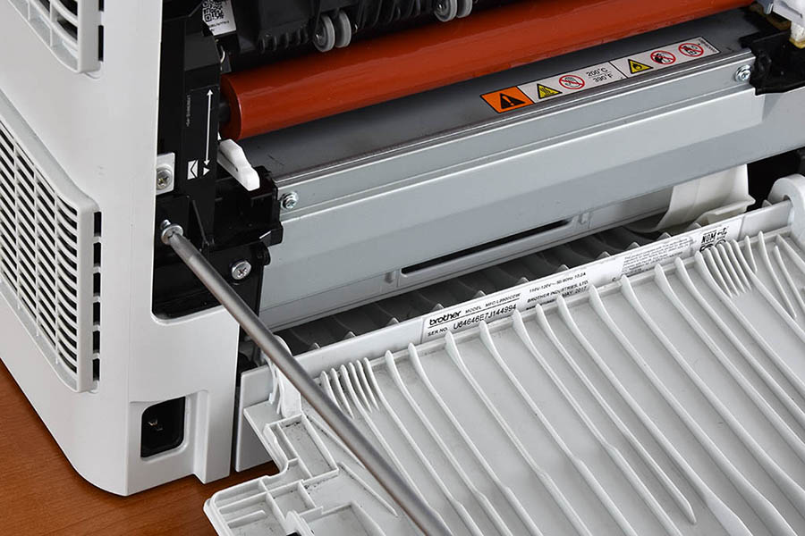
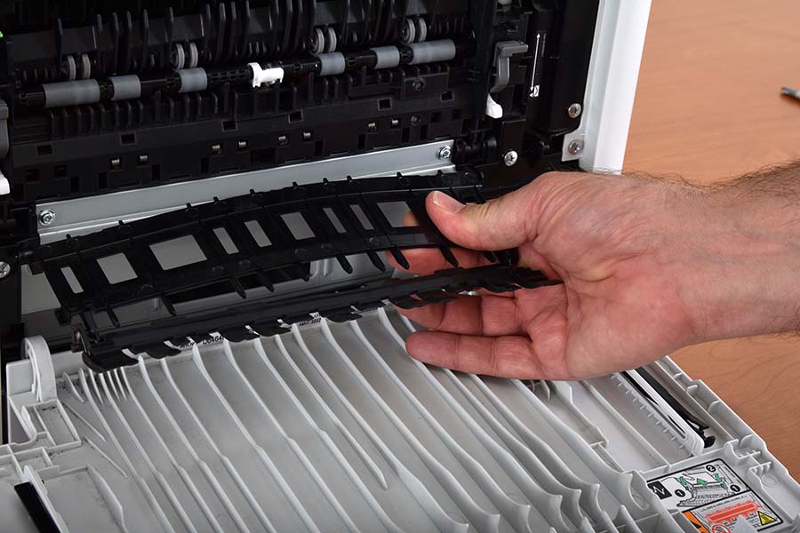
- Remove the inner guide by gently bending the guide in an upward motion. When slightly bent, the tabs that hold the guide in place should release from the printer framing.
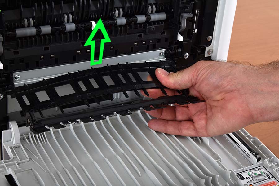
Remove the inner guide by slightly bending it in an upward motion
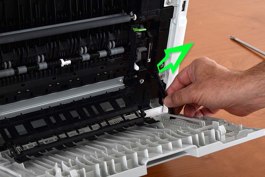
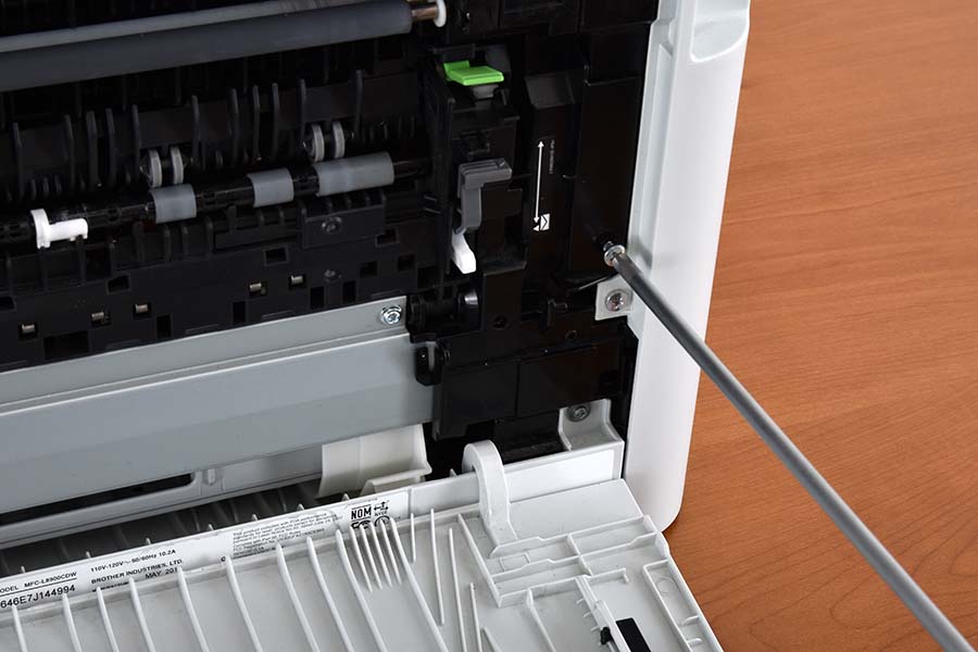
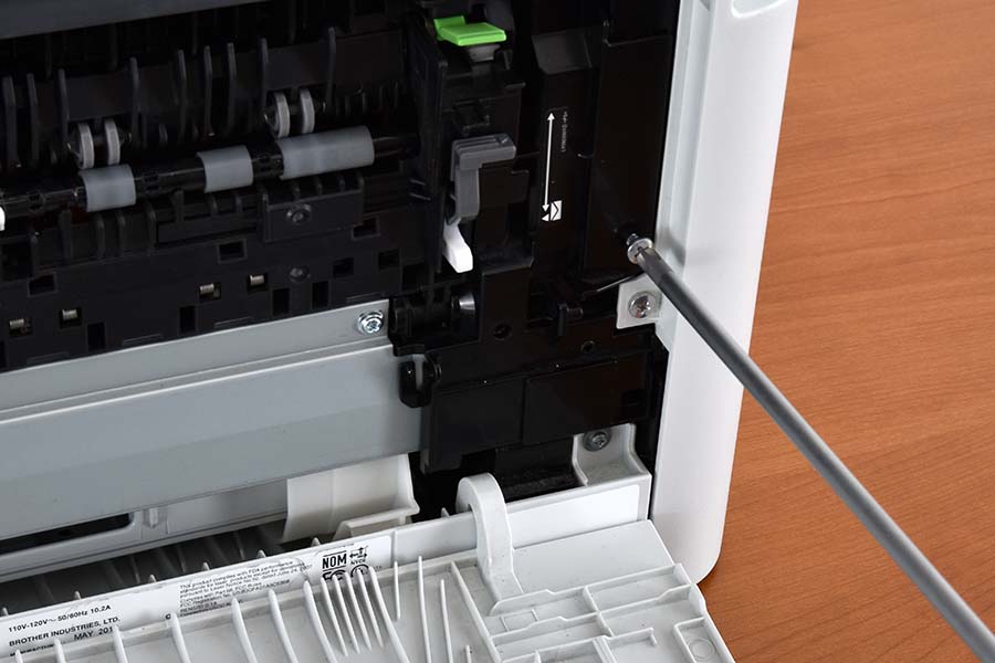
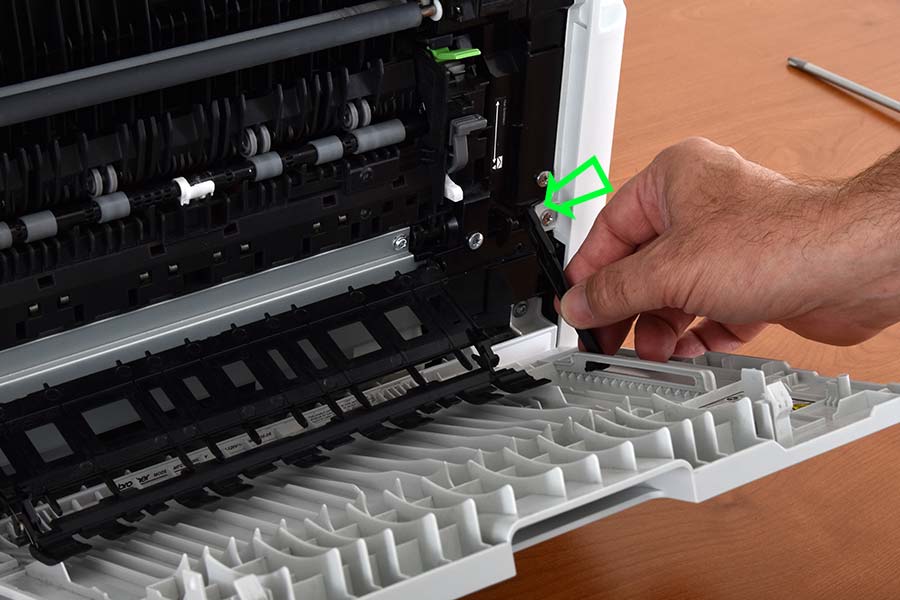
- Remove the right fuser cover by removing the two screws as shown in the photos below. A philips head screwdriver is required. With the two screws removed, lift the tab in the lower right corner to release the right fuser cover. Slide the cover out by pulling outward from the bottom.
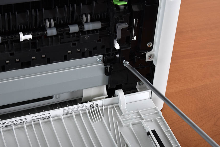 
Remove right fuser cover lower screw
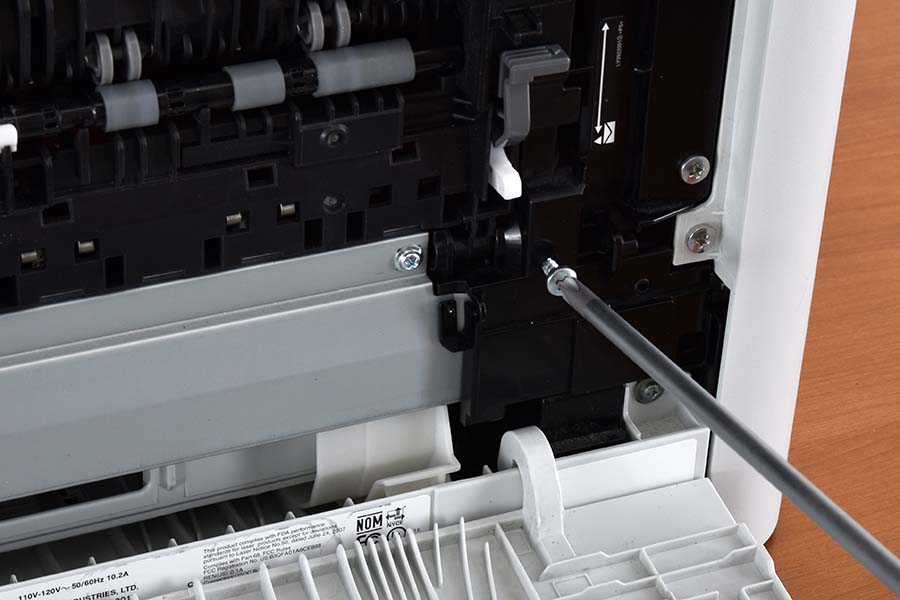
Remove right fuser cover upper screw
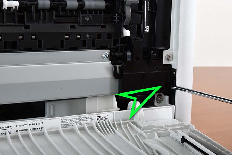 
Gently lift the right fuser cover release tab to allow removal of the cover
Remove right fuser cover by pulling outward from the bottom
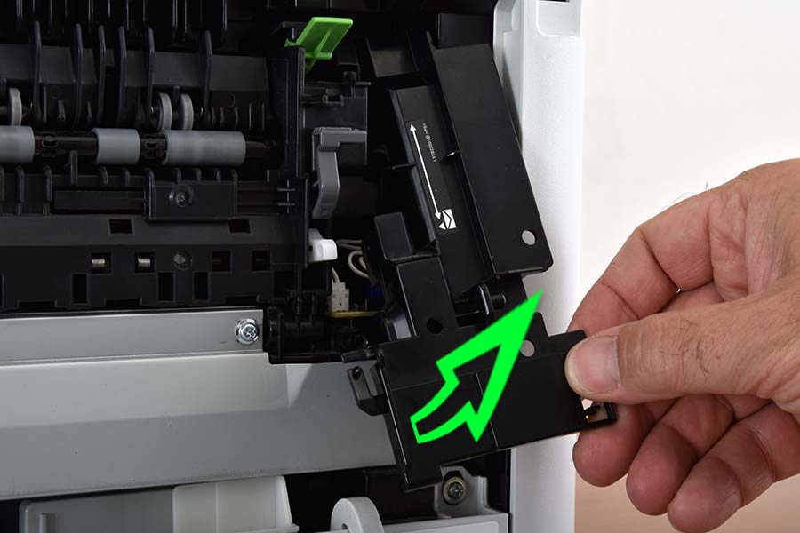
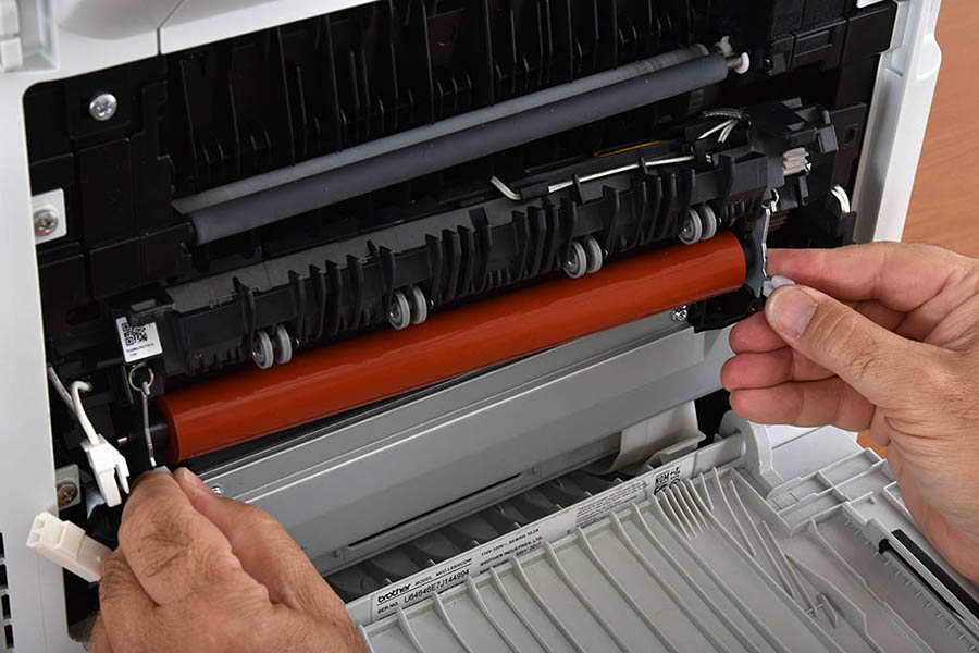
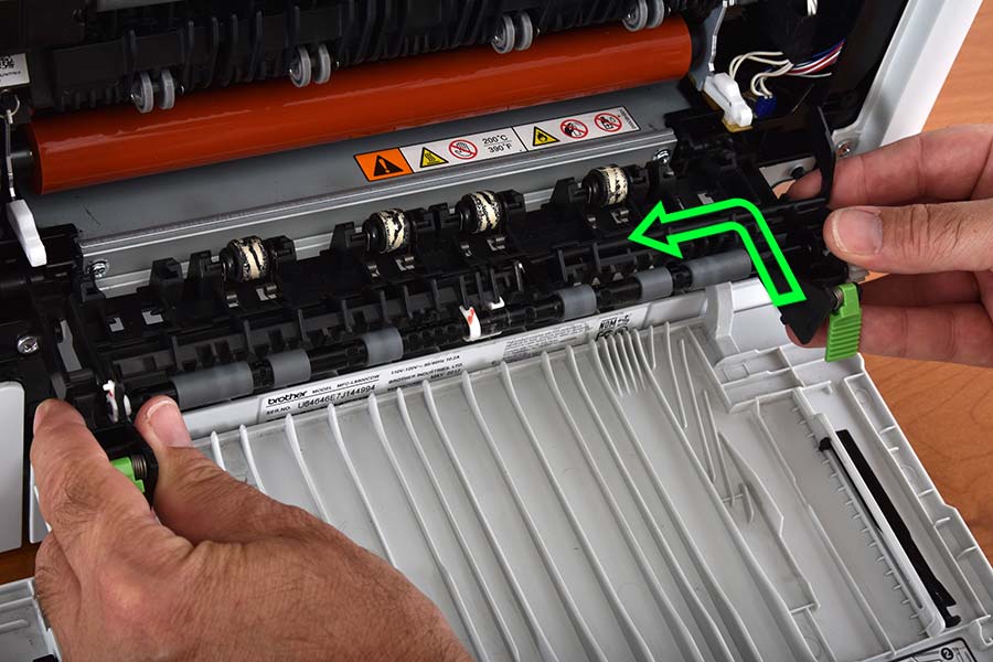
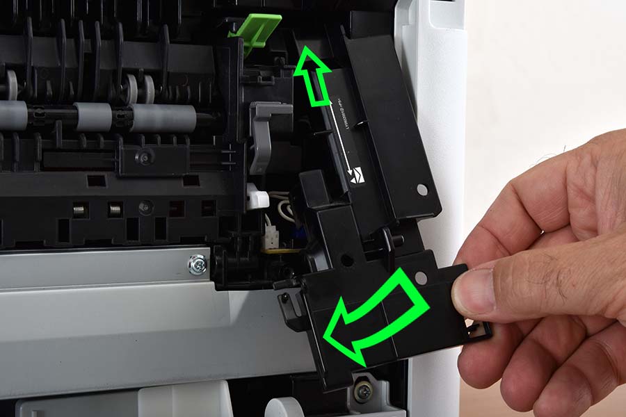
- Remove the exit pinch roller assembly by sliding the assembly to the right, and pulling outward.
Remove pinch roller assembly by sliding to the right and pulling outward.
- Remove the left fuser cover by removing the two philips head screws as pictured, then lift the tab in the center left to release the cover. Gently lift and pull the cover outward from the bottom to remove it.
Remove left fuser cover upper screw
Remove left fuser cover lower screw
Gently lift the left fuser cover release tab to allow removal of the cover
Remove left fuser cover by pulling outward from the bottom
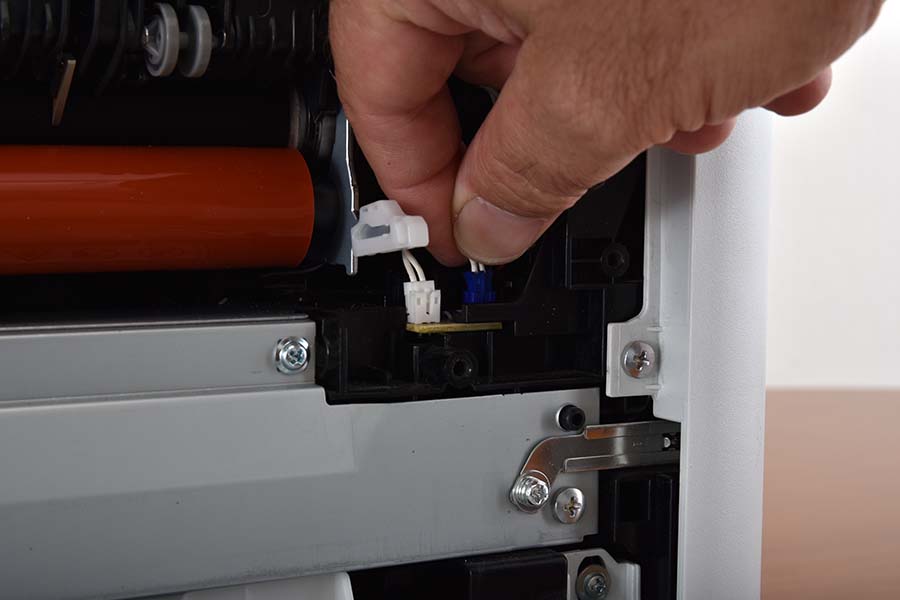
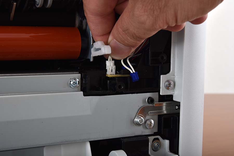
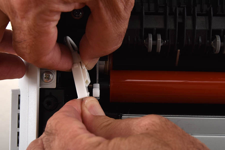
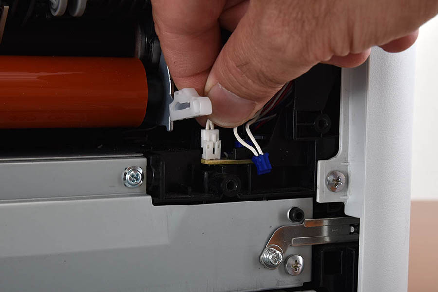
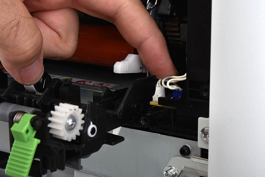
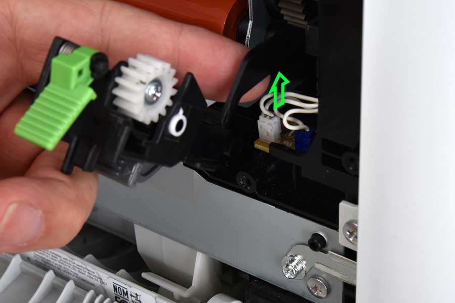
- Disconnect the fuser wiring on the left side of the fuser unit by pressing the clip (as shown) and pulling on both ends of the wiring harness. Detach the wiring on the right side of the unit by pulling the two wires up from the attached circuit board.
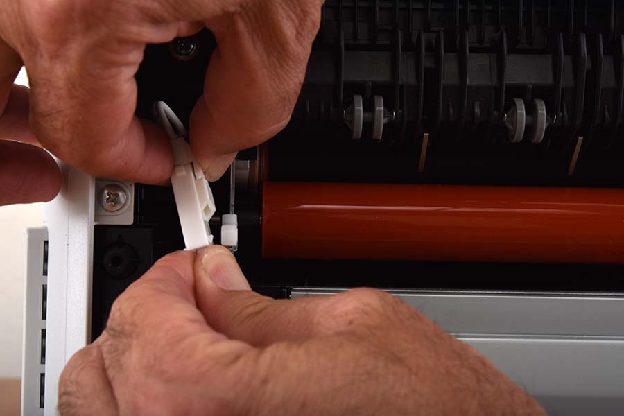 
Disconnect left fuser wiring by pulling both ends of the wiring harness
Disconnect right fuser wiring by pulling up on the wiring harness
Disconnect right fuser wiring by pulling up on the wiring harness
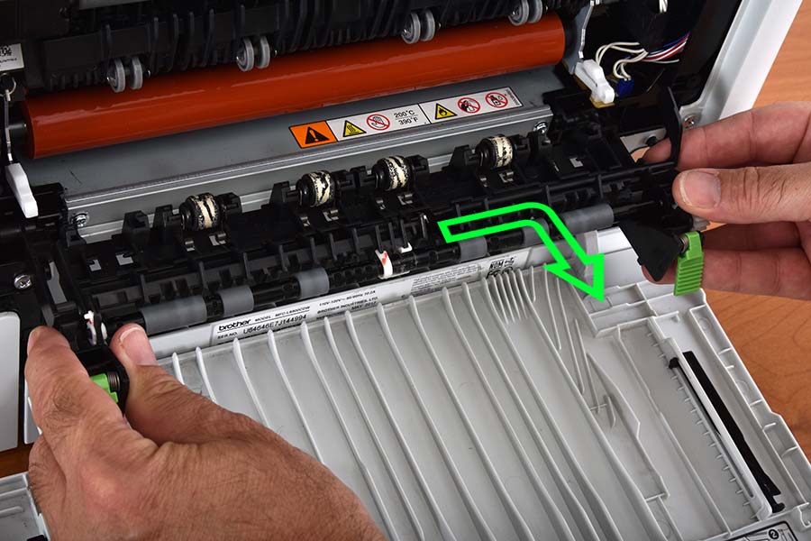
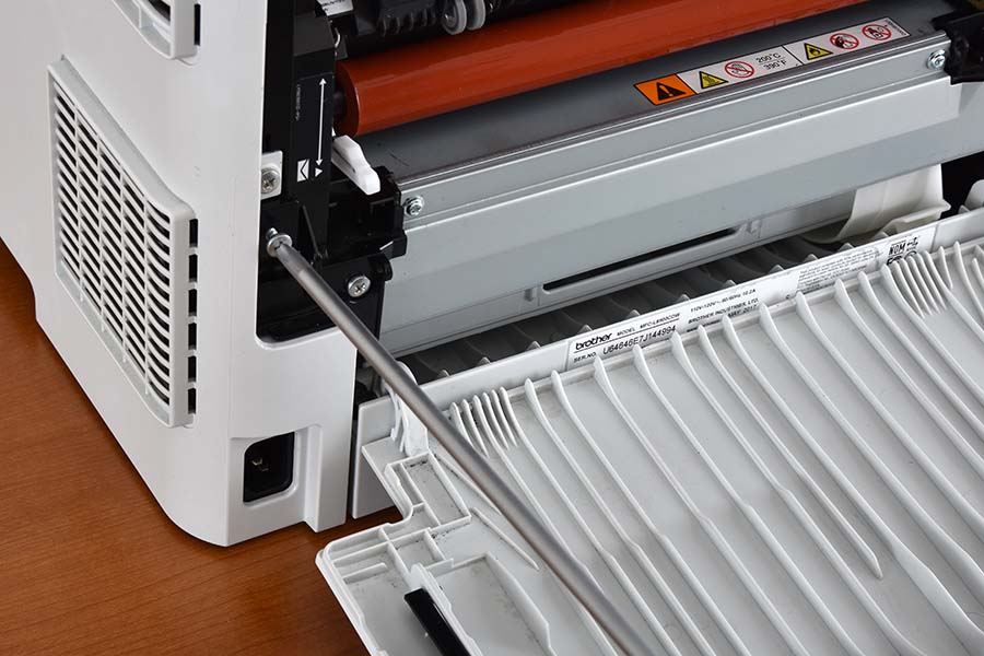
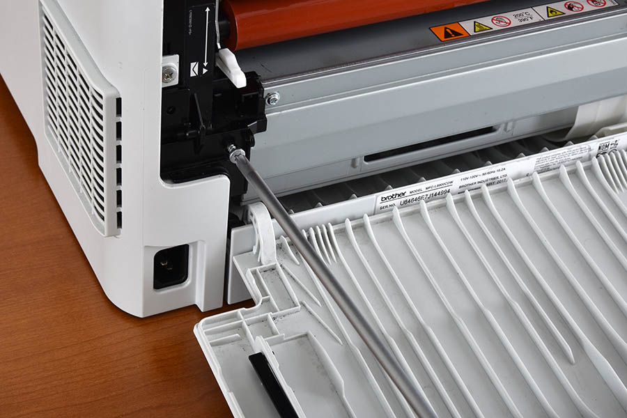
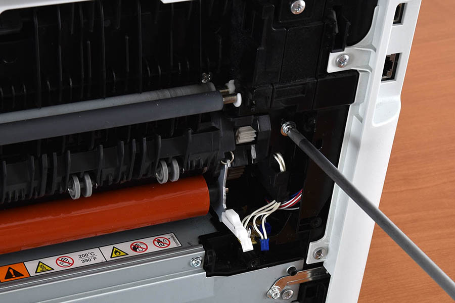
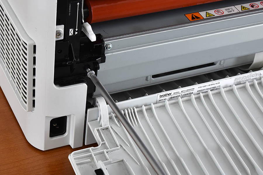
- Remove the fuser assembly by removing the philips head screws on each side of the fuser unit. Once the screws are removed, pull on the plastic pull tabs starting with the right side of the fuser unit to dismount the assembly. Once the assembly becomes loose, proceed to fully remove the fuser unit by pulling the entire assembly outward.
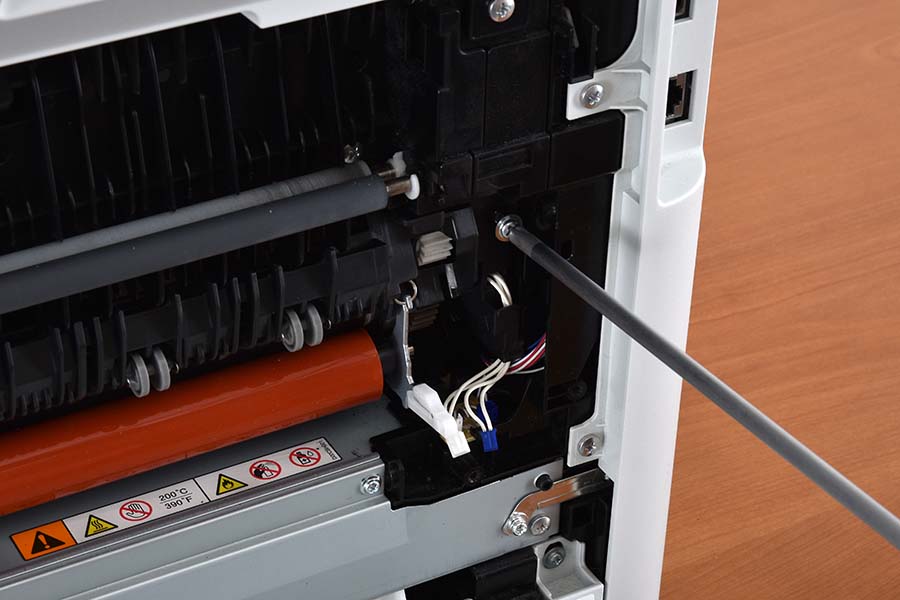 
Remove fuser assembly right screw
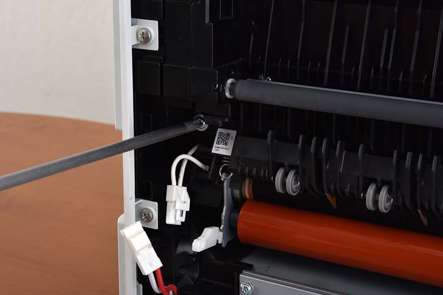
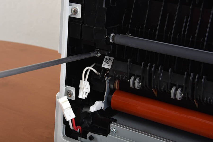
Remove fuser assembly left screw
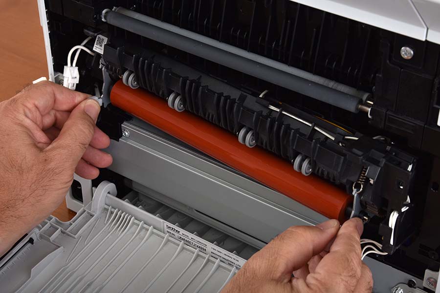
Remove fuser assembly by pulling it outward
Step 2: Replace toner filter
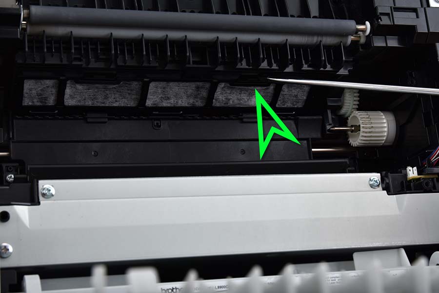
- Press inward on the two clips securing the toner filter. This will allow for easy removal of the old toner filter.
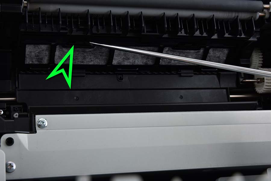 
Press inward on the left clip
Press inward on the right clip
- Drop the toner filter down, allowing the three tabs on the back to drop out of their slots.
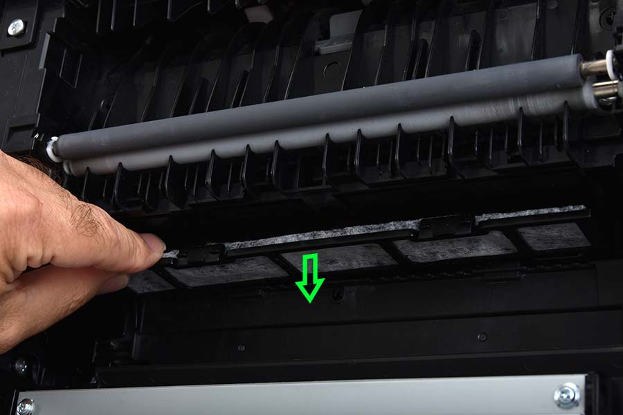
Pull the toner filter down
- Slide the three tabs of the new toner filter into the slots. Rotate the toner filter upward until the two clips snap into place, securing the new toner filter.

Slide tabs into new slots and press upward to install the new toner filter
Step 3: Replace exit pinch rollers
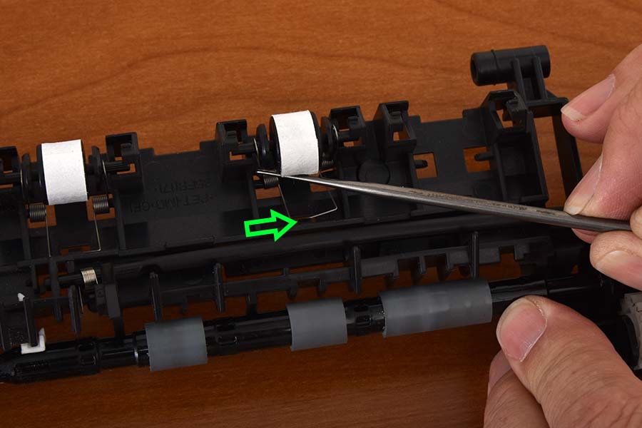
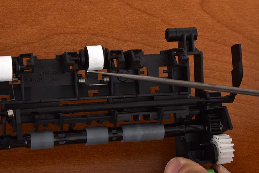
- Using either a spring hook or flat head screwdriver, slide one side of the pinch roller spring off its post. A spring hook tool is highly recommended for this step.
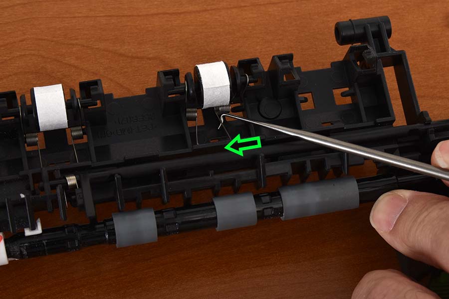
Slide pinch roller spring off right post
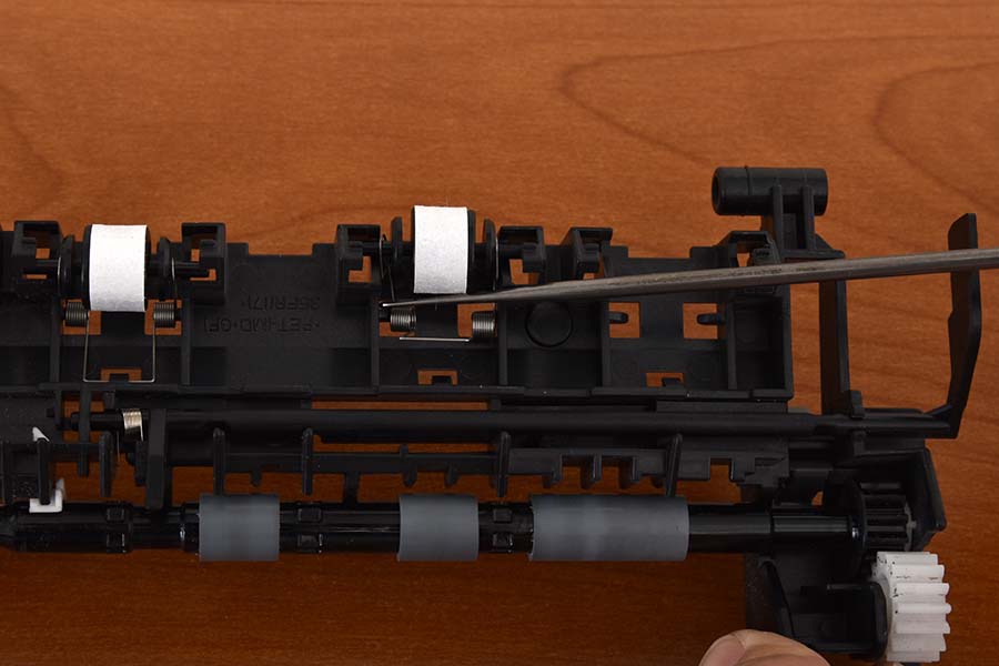
- Slide the other side of the pinch roller spring off its post. We highly recommend a spring hook tool for ease of removal.
Slide pinch roller spring off left post
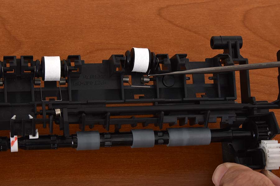
- Slide the pinch roller upward and outward through the slots to release it from the assembly.
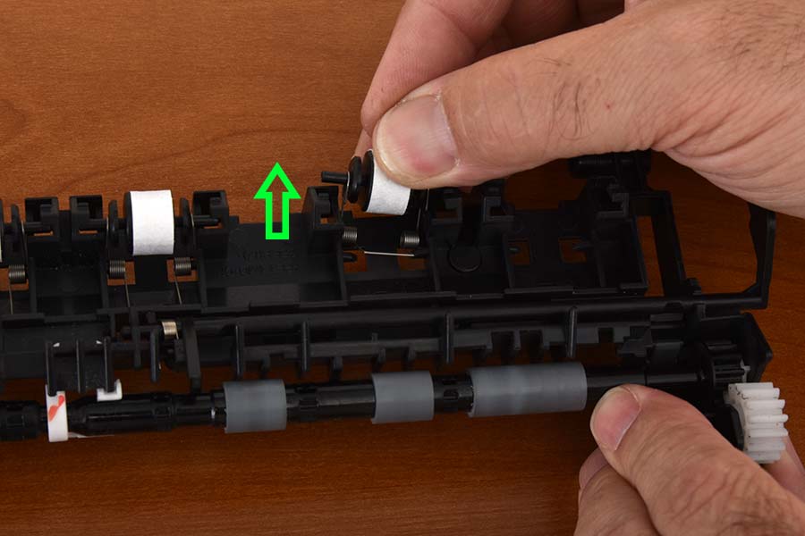
Slide through the slots to release the pinch roller
- Gently widen the spring to remove the pinch roller.
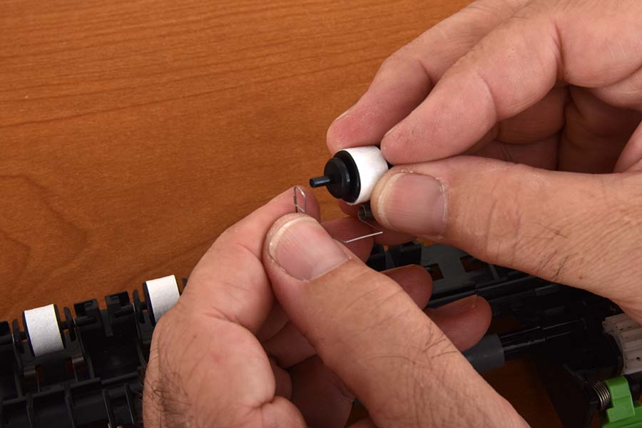
Widen spring and remove pinch roller
- Gently widen the spring again to insert the new pinch roller.
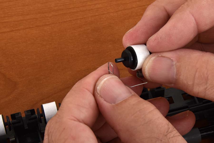
Widen spring and insert new pinch roller
- Slide the pinch roller back into the assembly through the slots on the outer edge, with the spring angle opening upward, matching the other springs. It is easiest at this point to keep the spring held slightly upward from the assembly. Rotate the spring downward into the assembly, but not far enough to clip the lower edge at this time.
Install pinch roller into assembly by sliding the roller into the assembly through the slot and rotating it downward
- Slide the left loop of the spring over its corresponding post. The loop should be fully over the post to keep the spring from dislodging.
Slide loop of the spring over left post
- Slide the right loop of the spring over its corresponding post. Again, make sure that the loop is fully over the post to prevent the spring from becoming dislodged.
Slide loop of the spring over right post
- Push the flat bottom edge of the spring under the retaining tab in order to properly secure the spring into place.
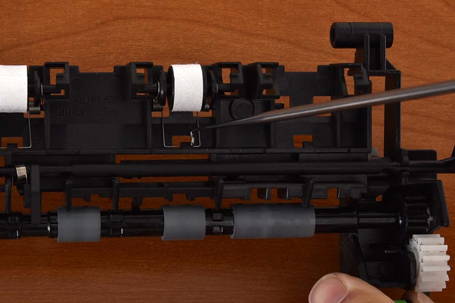
Secure the spring by pushing the bottom edge under the retaining tab
- Repeat steps 1 through 9 for the remaining 3 pinch rollers.
Step 4: Install the new fuser
- Install the fuser assembly by sliding the new unit into the machine, then shift gently in place until the fuser unit seats fully back and aligns with the screw holes. Insert and tighten the philips head screws on each side of the fuser unit.
Install fuser assembly unit by shifting gently until fuser aligns with screw holes
Tighten fuser assembly unit right screw
Tighten fuser assembly unit left screw
- Reconnect the fuser wiring on both the left and right sides of the fuser.
Reconnect left wiring
Reconnect right wiring
- Adjust the position of the wires to allow smooth operation of the exit sensor. Without properly adjusting these wires, you may have difficulty attaching the fuser covers, and your printer may mistakenly report paper jams.
Adjust wire position to avoid false paper jam errors
- Install the left fuser cover by inserting the tab on the top of the cover behind the framing. Rotate the bottom part of the cover inward until the lower tab snaps into place. Insert and tighten the two screws that were previously removed.
Insert the tab of left fuser cover behind framing
Insert and tighten fuser cover bottom screw
Insert and tighten left fuser cover top screw
- Install the exit pinch roller assembly by sliding the assembly inward and to the left once the posts are aligned with their slots. Then, rotate the assembly upward while holding sensor arm up until the assembly latches into place.
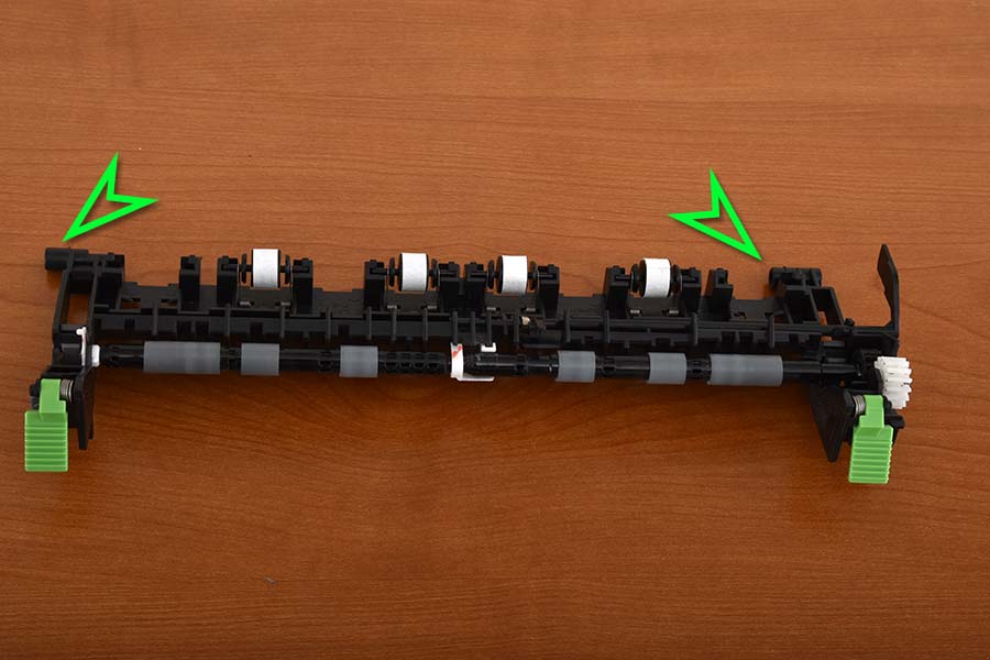 
Pinch roller assembly posts to insert into covers
Slide exit pinch roller assembly inward and to the left once the posts are aligned with their slots
Lift sensor arm over wiring connectors
- Install the right fuser cover by inserting the post at the top of the cover into the hole in the printer frame, then rotating the bottom of the cover inward until it snaps into place. Insert and tighten the two screws that were previously removed.
Install right fuser cover by inserting the tab and rotating the cover
Insert and tighten right fuser cover top screw
Insert and tighten right fuser cover bottom screw
- Install the inner guide by inserting the left tab into the left cover, and then flexing the guide upward until the right tab inserts into the right cover.
Install the inner guide by flexing it until the right tab inserts
- Reattach the door support arms as shown in the photos below. They should snap easily onto the posts.
Support arm locations
Attach support arms by snapping them into place
- Close the printer exit door.
- Plug the printer back in and turn the printer on.
Step 5: Reset the fuser life counter
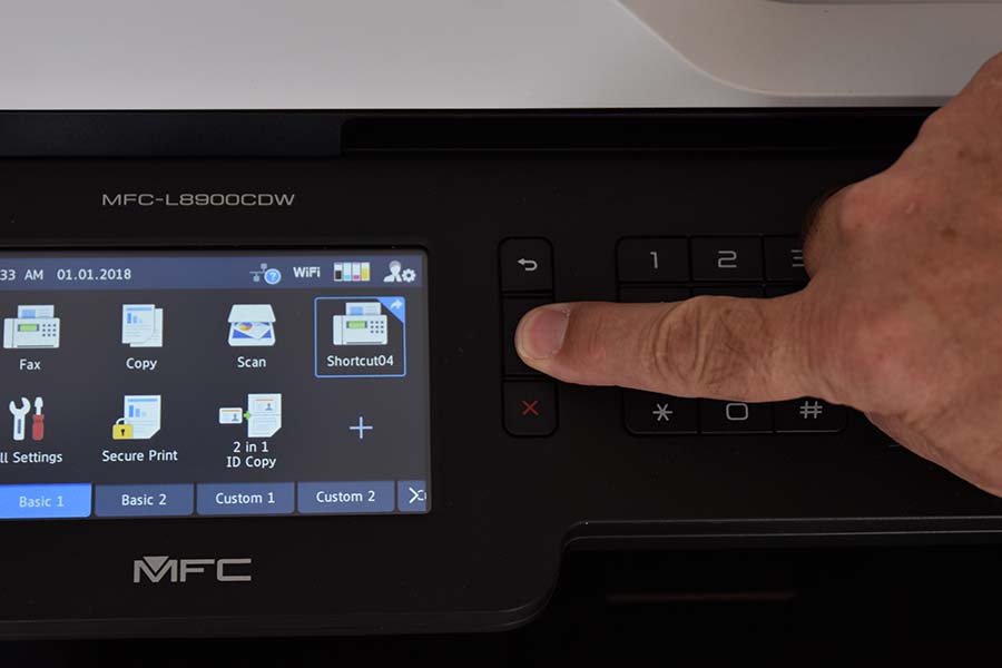
- With the printer initialized and in ready to print mode with the home screen showing on the display, press and hold the home icon for 5 seconds to show the Serial No. & ROM Version screen.
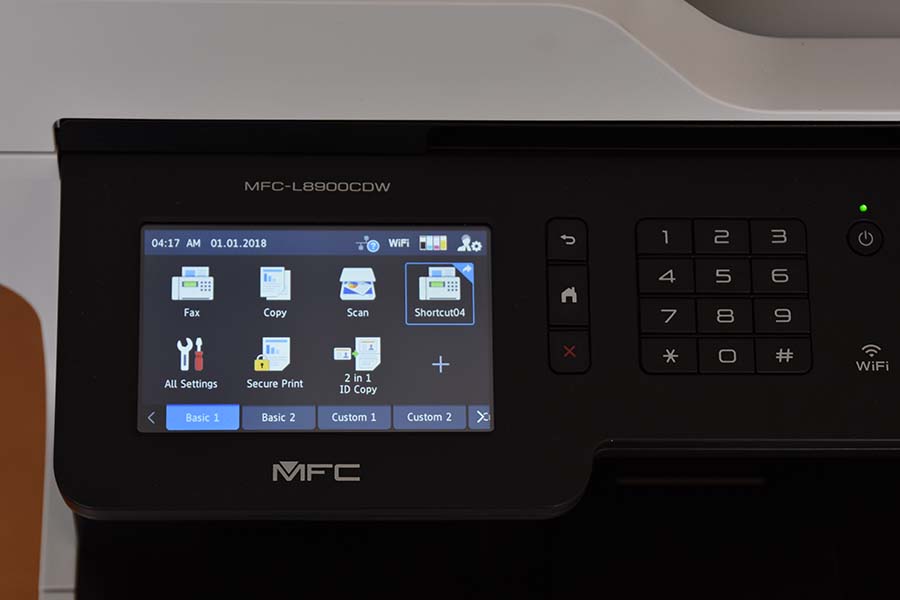 
Home screen as shown
Press and hold down the home button
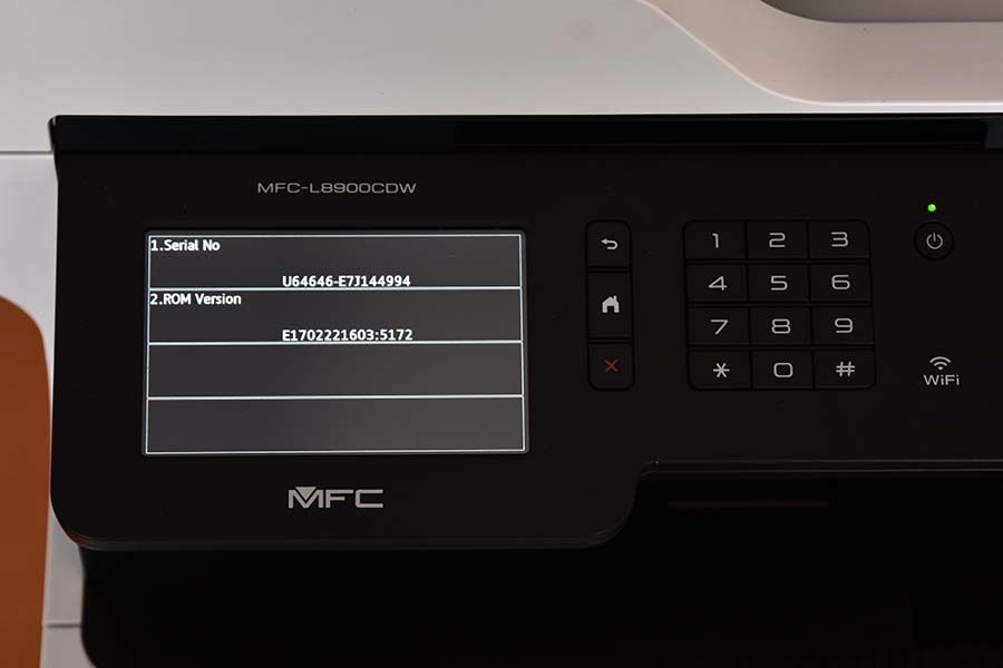
Serial number & ROM version shown on screen
- Tap the bottom blank section.
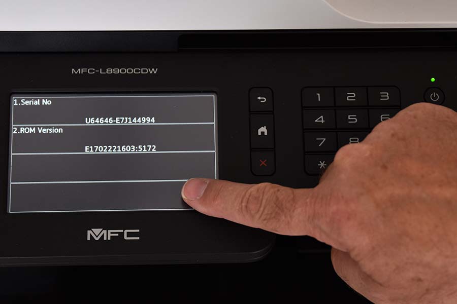
Press the blank section on the display
- Tap *, 2, 8, 6, 4 on the display to enter Maintenance Mode.
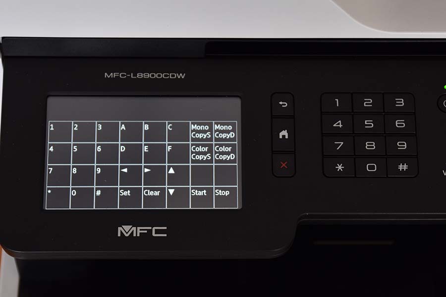 
Screen prior to maintenance mode
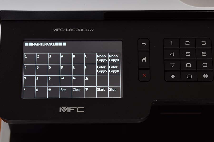
MFC-L8900 in maintenance mode
- Tap 88 on the display to enter the “Reset counters for consumable parts” mode.
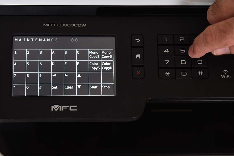
Press 88 to enter reset counters mode
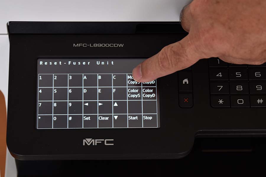
- Tap the up arrow on the display until you see “Reset - Fuser Unit.”
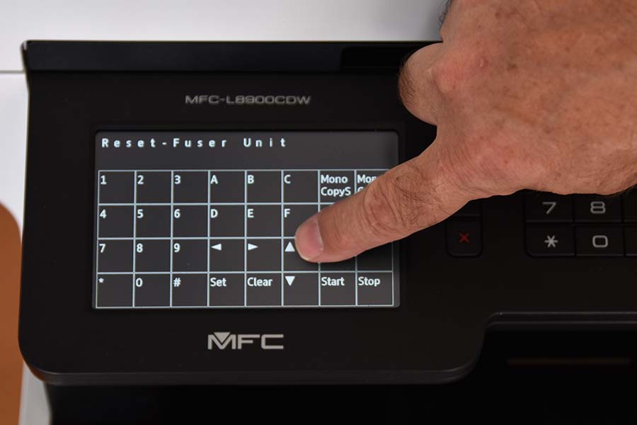 
Press the up arrow to select fuser unit
Reset fuser unit as shown on the LCD display
- Tap Mono CopyD on the display. ”Fuser OK” should appear on the display.
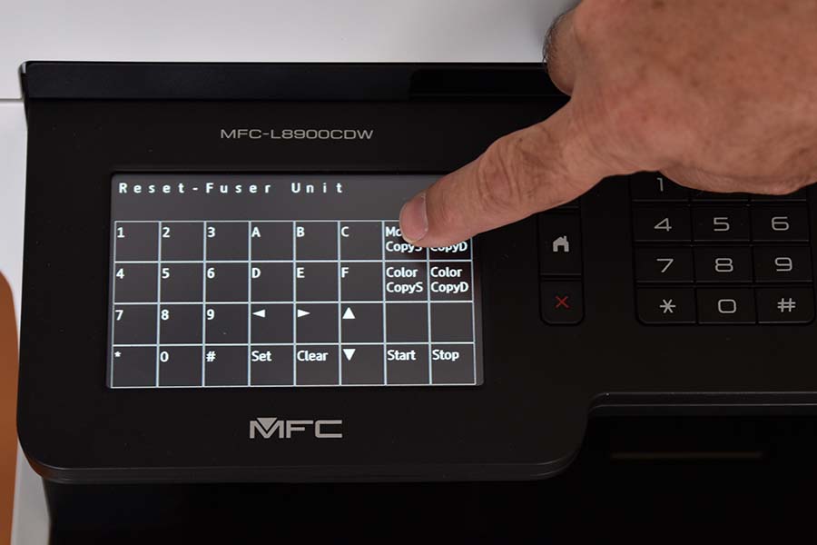 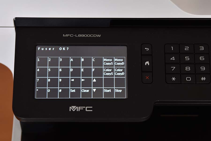
Select Mono CopyD to on the display to confirm reset of your fuser unit
Fuser ok as shown on the LCD display
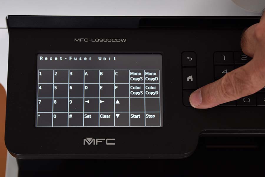
- Tap Mono CopyD again to confirm resetting the fuser counter. It will return to “Reset - Fuser Unit.”
Select Mono CopyD to again confirm reset of your fuser unit
- Press the X key on the keypad to exit reset mode.
Press the X key to exit reset mode
- Tap 99 on the display to exit Maintenance Mode.
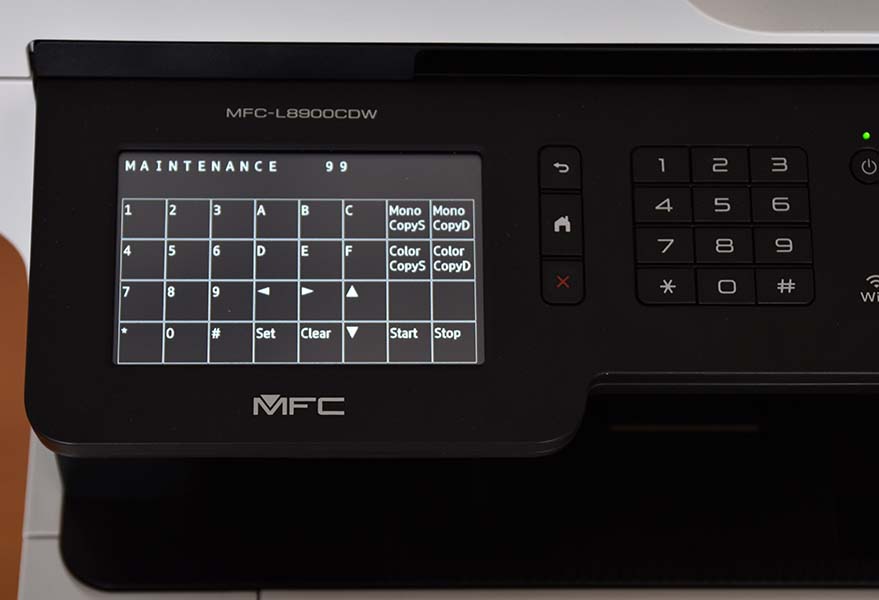
Press 99 either on the display or on the keypad to exit maintenance mode
- Publisher: Precision Roller
|
|


 Canon Drum Unit - Black / Color