Included with Maintenance Kit: (1) Transfer Roller (1) Charge Roller (1) Fuser Assembly (6) Pickup Rollers
Tools Required For Installation:
(1) Phillips Screwdriver (1) Standard or Flat Blade Screwdriver (1) Pair of latex gloves.
Before Installation: Turn the power off and unplug the power cord from the printer.
Caution: If you have been using the printer, the fuser section will be hot. Please allow the fuser to cool for at least 30 minutes before removing it.
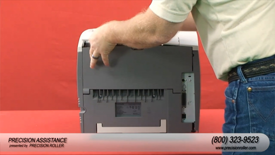
Removing The Fuser:
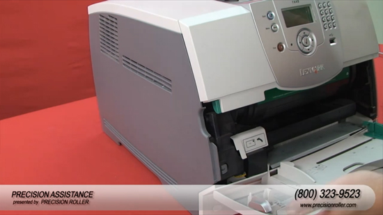
Remove the Redrive cap.
Remove the Redrive door by pulling up at a slight angle.
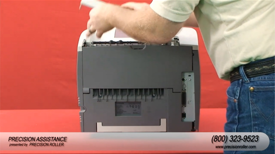
Remove the Fuser Cover by squeezing the two latches together and pulling the fuser cover up.
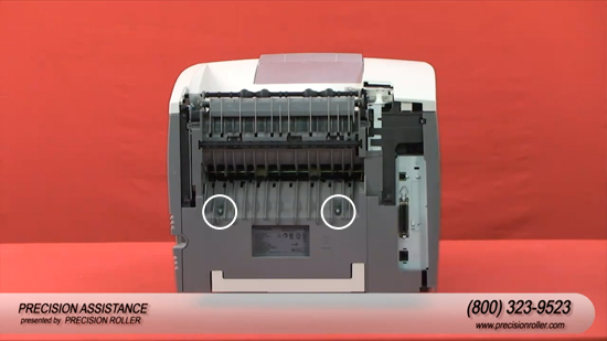
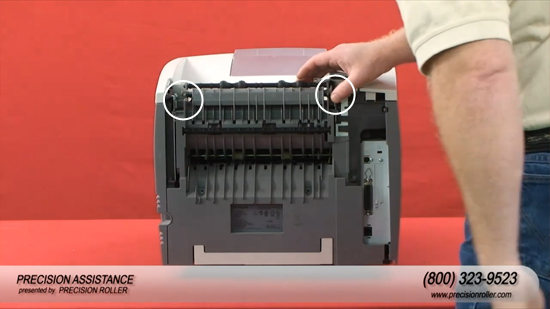
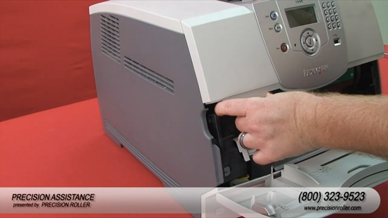
Remove the rear Redrive assembly by unscrewing the two mounting screws with a Phillips screw driver.
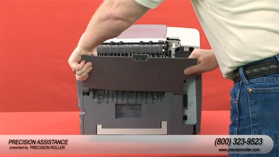
Locate the two clips holding the redrive in place and squeeze the two clips at the same time to release the Redrive.
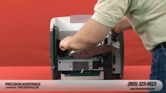
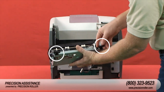
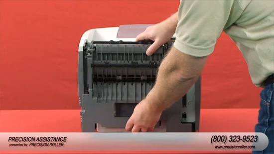
Slide the fuser assembly straight out of the printer.
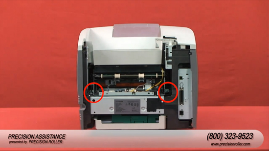
Note: In order to remove the fuser, you must first remove the two screws holding it in place with a Phillips screw driver.
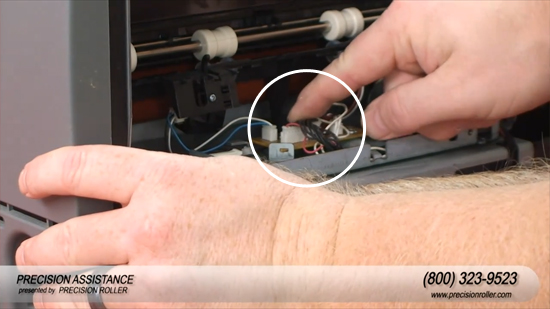
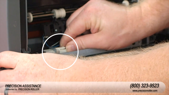
Next, disconnect the fuser sensor cable from the fuser control board. Finally, disconnect the fuser power cable.
Remove the fuser.
Installing the Fuser:
Before installing the new fuser, remove the two wedges that take the spring tension off the rollers.
Insert the new fuser into the printer and reinstall the fuser sensor cable to the fuser control board
Reinstall the fuser power cable.
Reinstall the two screws that hold the fuser into place with a Phillips screw driver.
Reinstall the rear Redrive assembly by snapping it into place.
Reinstall the two mounting screws with a Phillips screw driver.
Reinstall the Redrive door by sliding it in at a slight angle.
Reinstall the Redrive cap by snapping it into place.
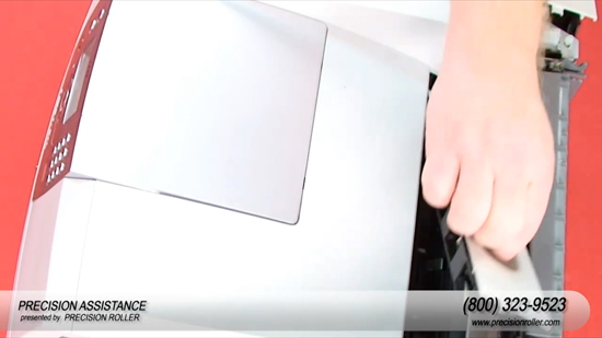
Removing the Transfer Roller:
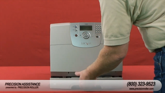
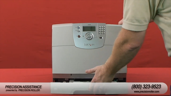
Turn the printer around so the front is facing you
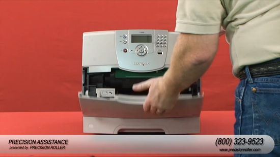
Open the lower guide door.
To open upper front door squeeze the green tab.
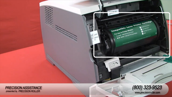
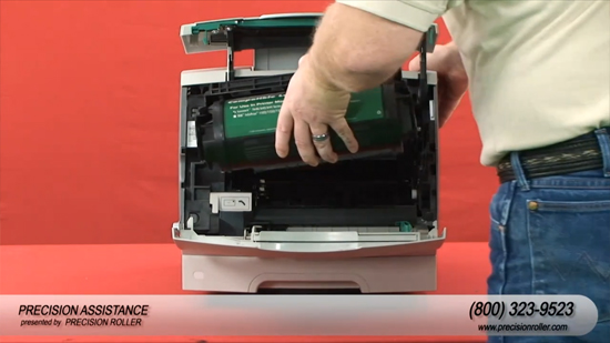
Remove the toner cartridge.
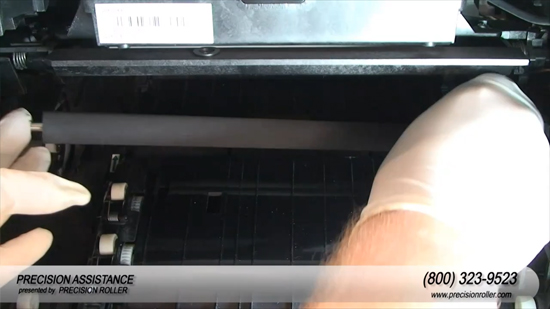
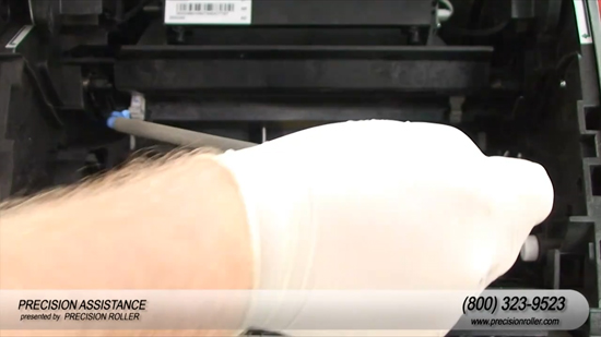
Using a flat blade screw driver, unsnap the Transfer Roller Assembly from the left pivot arm
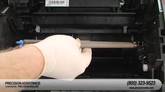
Lift the Transfer Roller Assembly toward the left and remove it from the printer.
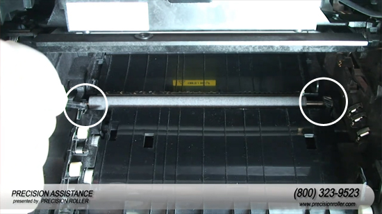
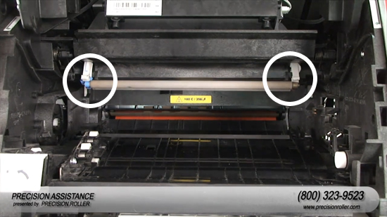
Install the new replacement transfer roller by sliding in the right pivot arm with the gear end.
Slide the left side in until it snaps into place.
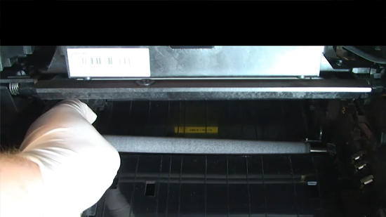
Locate the charge roller toward the rear of the opening just above the transfer roller by slightly lowering top front door.
Remove the charge roller by grasping the left side and slightly pulling it down until it unsnaps.
Grasp the right side and slightly pull it down until it unsnaps.
Remove the charge roller from the printer.
Reinstall the new replacement charge roller by slightly lowering top front door and gently snapping the left side into place.
Gently snap the right side into place.
Reinstall the toner cartridge and close the front door and the lower guide door.
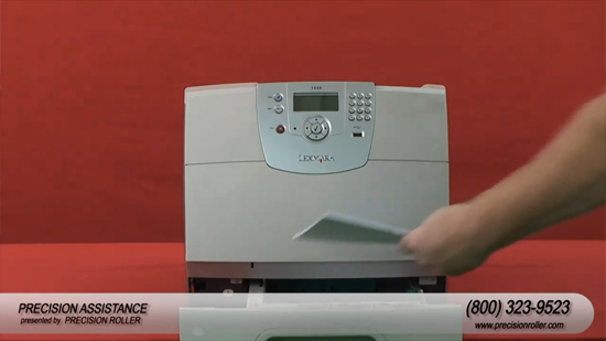
Remove any paper remaining in the paper tray, and then remove the paper tray from the printer.
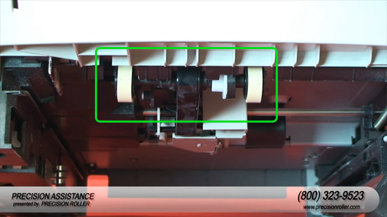
Pay close attention to the area of the printer where the paper tray was installed. Carefully locate the auto pick arm assembly. It is along the ceiling/top of the area and contains a black plastic arm in the shape of a "T". The pickup roller should be visible on the end of the “T”-shaped arm. (Each pick roll is a rubber tire mounted on a black plastic wheel.)
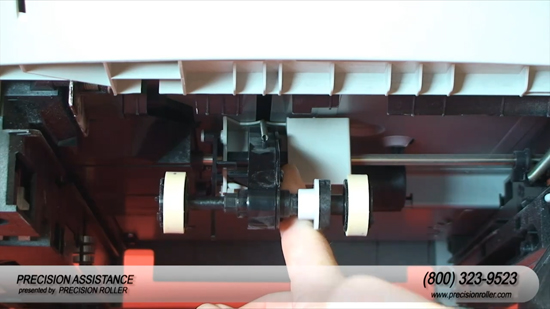
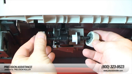
Pull the black plastic arm down. A tab should be visible on each shaft which each pick roll is mounted.
Gently push the tab in towards the center of the wheel.
Caution: Do not use excessive pressure on tab. The tab may break.
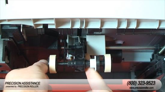
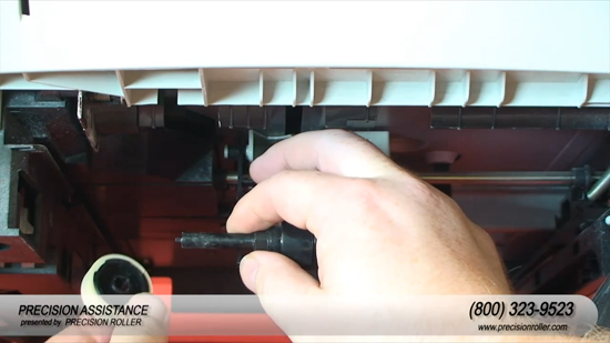
While holding in the tab, remove the old pickup roller.
Snap the new pickup roller onto the shaft.
Confirm that the roller is securely installed on the shaft.
Reinsert the paper tray by sliding it into place.
Reset Maintenance Count
Reinsert the power cord into the rear of the printer in order to provide power.
Turn off the printer.
Press and hold (check) and .(right arrow).
Turn on the printer.
Release the buttons once the Performing Self-Test displays "CONFIG MENU" on the top line of the operator panel.
Select "Reset Maintenance Count" from the Configuration menu.
The message "Reset Maint Cnt=Reset" displays momentarily. Press (check) to reset.
Note: When the reset operation is complete, the menu returns to the Printer Setup Reset Maintenance Count Screen.
Scroll down to the Exit Configuration Menu and Press the "Select" button in order to return to "Ready" status.
Individual brands are copyrighted by their respective owners. Precision Roller is in no way affiliated, sponsored or endorsed by these copyright owners or their affiliates or dealers
This website uses a secure server to encrypt all sensitive information.


 HP 55X Black High Yield Toner Cartridge