


|
HP LaserJet 4000 Removing Covers and External Components
Originally written for: HP LaserJet 4000
Also applies to: HP LaserJet 4000n, 4000se, 4000t, 4000tn, 4050, 4050n, 4050se, 4050t, 4050tn

These instructions explain removing the covers and external components of an HP Laserjet 4000 and similar models. Contents
IntroductionThis document explains how to remove exterior components such as covers and the control panel from your HP LaserJet 4000 printer. Removing the Control Panel
Removing the Front Right Side Cover
Note: When you reinstall the front right side cover, be sure to reconnect the power switch rod.
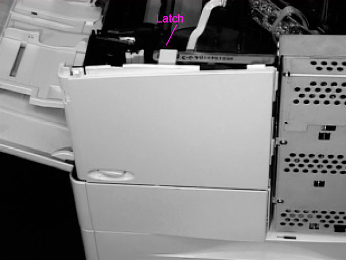
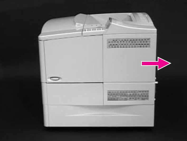
Removing the Left Side Cover
Removing the Rear Right Side CoverNote: The Formatter and dual in-line memory modules (DIMMs) are located underneath the Right Side Cover.
Removing the Rear Cover/Rear Output Bin
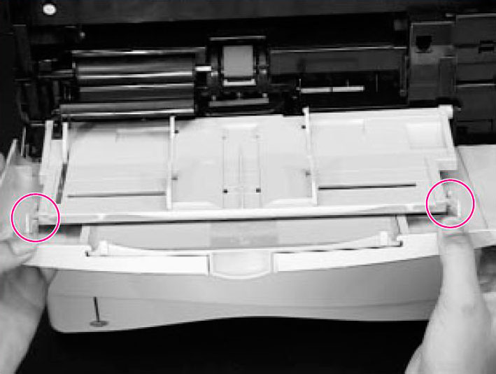
Removing Tray 1 from the Front Cover
Note: When you reinstall the Tray 1 Sensor Arm Cover be sure the Sensor Arms move freely.
|


 Atrix 31700C High Performance Vacuum Filter


©2003-2024 Precision Roller. • 2102 West Quail Avenue, Suite 1 • Phoenix, AZ 85027 • (800) 323-9523 / (623) 581-3330 • M-F 8:00am - 4:30pm MST (noDST)
Individual brands are copyrighted by their respective owners. Precision Roller is in no way affiliated, sponsored or endorsed by these copyright owners or their affiliates or dealers
This website uses a secure server to encrypt all sensitive information.
Questions? Concerns? Send us a note at webmaster@precisionroller.com
This website uses a secure server to encrypt all sensitive information.
Questions? Concerns? Send us a note at webmaster@precisionroller.com