Originally written for: HP LaserJet 2100
Also applies to: HP LaserJet 2100m, 2100se, 2100tn, 2100xi
These instructions will help explain maintenance kit installation steps for an HP Laserjet 2100 and similar models.

HP LaserJet 2100
Contents
- Introduction
- Replacing the transfer roller
- Replacing the Tray 1 Pickup Roller Assembly and Separation Pad Arm Assembly
- Replacing the Tray 2 Pickup Roller Assembly
- Replacing the Tray 2 Separation Pad Assembly
- Replacing the fuser assembly
Introduction
These seven regular maintenance items are available in the HP Laserjet 2100 maintenance kit (PN C4170-67901, H3974-60001)
This kit includes:
- (1) New Fuser Assembly [RG5-4132-000]
- (1) Transfer Roller [RG5-4164-000]
- (1) Tray 1 Pickup Roller [RB2-2900-000]
- (1) Tray 1 Separation Pad Arm Assembly [RB2-6348-000]
- (1) Tray 2 Pickup Roller [RB2-2891-000]
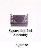
- (1) Tray 2 Separation Pad Assembly [RB9-0695-000]
- (1) Pair of Rubber Gloves (PR# S5800)
Required tools: a small flat-blade screwdriver (PR# T4700), a medium-sized flat-blade screwdriver (PR# T4710), a #2 Phillips screwdriver (PR# T4590), and a pair of needle-nose pliers (PR# T1420).
CAUTION: Wear rubber gloves while handling the new Transfer Roller, Separation Pads and Pickup Rollers. Finger oils and dirt can damage the Transfer Roller surface and reduce the effectiveness of the Separation Pad and Pickup Rollers.
Replacing the transfer roller
-
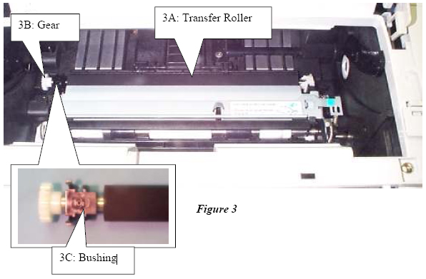
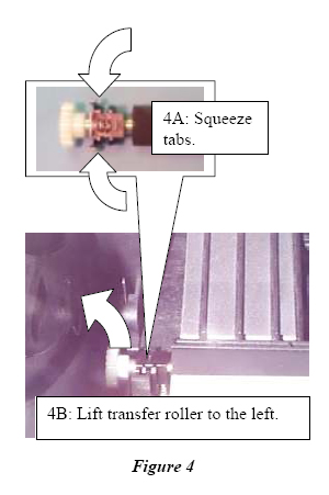
Open the toner cartridge door and remove the toner cartridge. Locate the transfer roller’s black bushing (Figure 3C), which is on the left end of the transfer roller (Figure 3A) shaft and just behind the gear (Figure 3B).
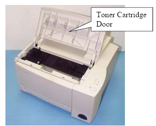
Toner Cartridge Door
-
Squeeze both of the black bushing’s tabs (Figure 4, Item 4A) and then lift the transfer roller’s shaft to the left (Figure 4, Item 4B) to remove the transfer roller.
-
Put on rubber gloves, then install the new transfer roller by performing steps 1 and 2 in reverse order.
Replacing the Tray 1 Pickup Roller Assembly and Separation Pad Arm Assembly
-
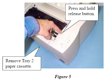
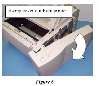
Remove the Tray 2 Paper Cassette, then press and hold the release button on the right side cover. Grasp the front and rear of the right side cover and swing it out from the printer.
-
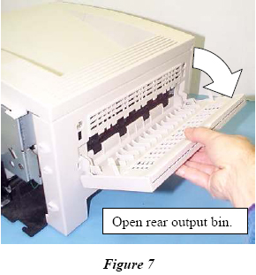
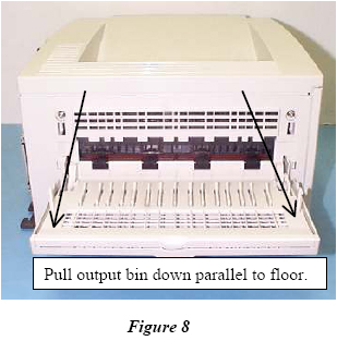
Open the rear output bin until it stops. Pull it again so that it rests parallel to the floor.
-
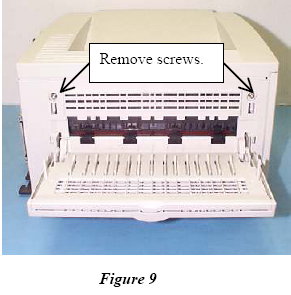
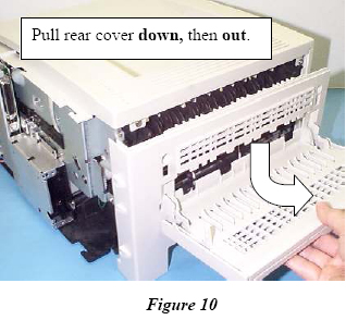
Remove the two rear cover screws. Pull the rear cover down and then out to remove it.
-
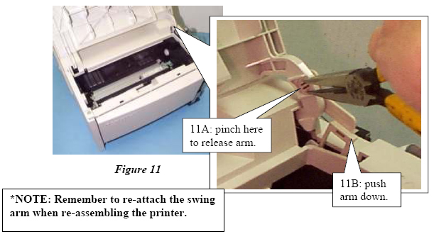
Release the swing arm* from the toner cartridge door (Item 11A), then push it down into the opening (Item 11B).
-
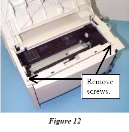
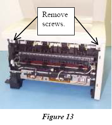
Remove the front and rear top cover screws.
-
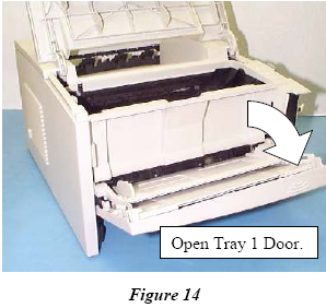
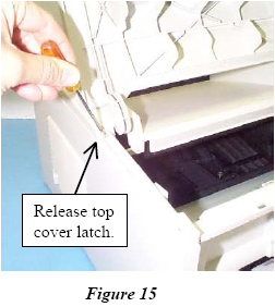
Open the Tray 1 door. Use a small flat-blade screwdriver to release the top cover latch.
-
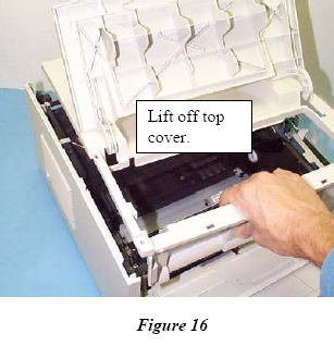
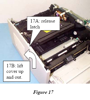
Lift the top cover off to remove it. Release the left cover latch (Figure 17A) then lift the cover up and outward (Figure 17B).
-
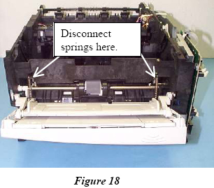
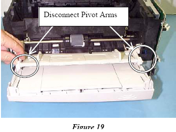
Using needle nose pliers, disconnect the Tray 1 Support Springs and Pivot Arms.
-
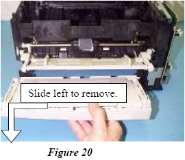
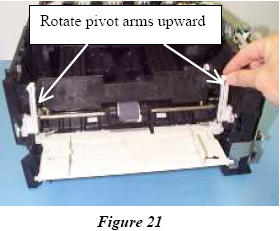
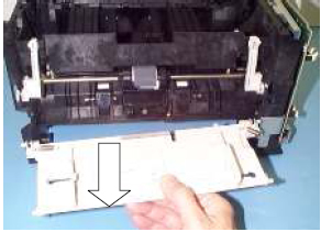
Remove the Tray 1 bottom piece by sliding it to the left. Rotate the pivot arms to the upward position.
-
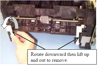
Remove the Tray 1 top piece. Rotate the pivot arms downward, and remove the pivot arms.
-
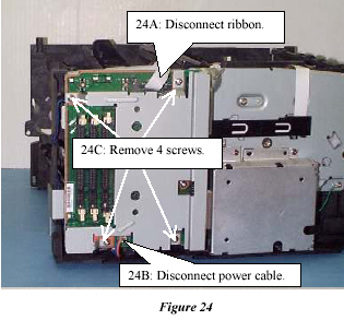
Disconnect the ribbon cable (Figure 24, Item 24A) and the power cable (Figure 24, Item 24B). Remove the four screws (Figure 24, Item 24C) from the metal RFI shield and carefully remove the shield.
-
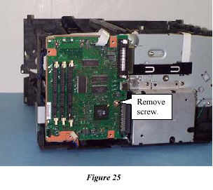
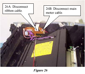
Remove the screw (Figure 25) from the Formatter PCB and remove the Formatter PCB. Disconnect the ribbon cable (Figure 26, Item 26A) and the main motor cable (Item 26B).
-
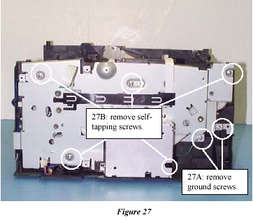
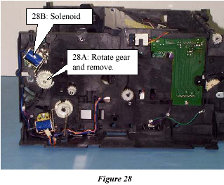
Remove the two ground screws (Item 27A) and the five self tapping screws (Item 27B).Lift the printer drive assembly out to remove it. Remove the Tray 1 drive gear (Item 28A) by pressing the release tab and rotating it to get it past the solenoid (Item 28B).
-
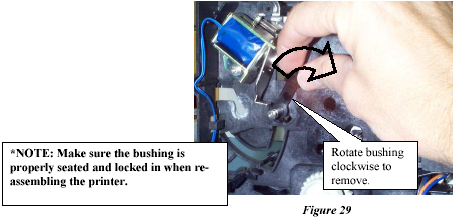
Remove the black right bushing by pulling out its lever and rotating it clockwise until the tab clears the keyed opening.
-
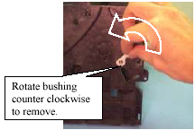
Turn the printer around and remove the white left bushing by pulling out its lever and rotating it counter clockwise until the tab clears the keyed opening.
-
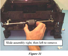
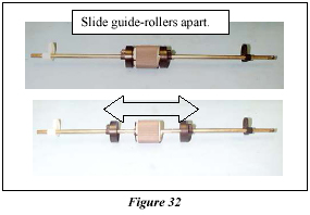
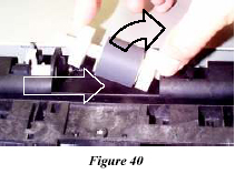
Slide the Pickup Roller Shaft Assembly to the right until the left end of the shaft clears the opening, then slide the assembly back to the left to remove it. Slide the two black guide rollers away from the Pickup Roller.
-
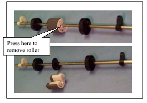
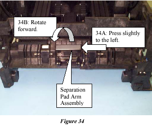
Press the release tab on the Pickup Roller and remove it from the shaft. Press the Separation Pad Arm Assembly slightly to the left (Item 34A), then rotate the Separation Pad Arm Assembly forward (Item 34B).
-
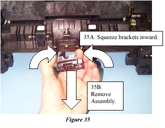
Squeeze both brackets inward (Item 35A) on the Separation Pad Arm Assembly, then remove it from the printer (Item 35B).
-
Put on rubber gloves, then install the new Tray 1 Separation Pad Arm Assembly and Pickup Roller by performing steps 1 through 18 in reverse order.
Replacing the Tray 2 Pickup Roller Assembly and Separation Pad Arm Assembly
-
Turn the printer top-downward with the front facing you.
-
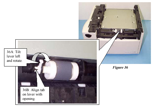
Tilt the white bushing lever to the left (Item 36A), then rotate the lever until the tab is aligned with the opening on the carriage (Item 36B).
-
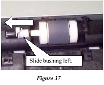
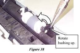
Slide the white bushing to the left and grasp the black bushing with needle nose pliers and rotate it until it points straight up.
-
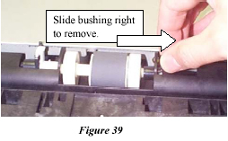
Slide the black bushing to the right and remove it. Slide the Pickup Roller Assembly to the right and remove it.
-
Slide the two white guide rollers off of the Pickup Roller.
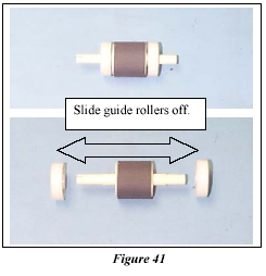
-
Install the new Pickup Roller by performing steps 5 through one, starting with step 5 and ending with step 1. Use rubber gloves during this procedure in order to prevent damage to the Pickup Roller.
Replacing the fuser assembly
-
Remove the right side cover and remove the rear cover.
-
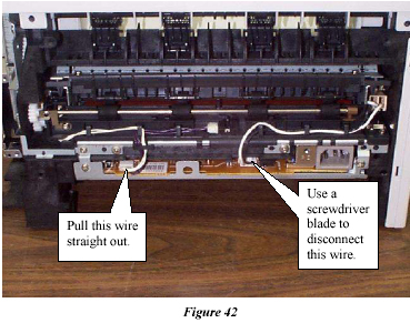
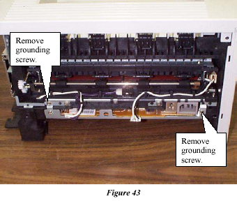
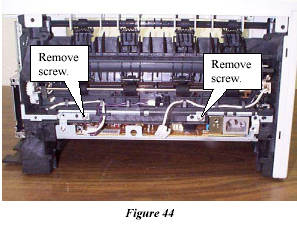
Disconnect the left wire by pulling it straight out and disconnect the right wire by pressing a flat blade screwdriver on the connector and then pulling the connector straight out. Remove the two grounding plate screws.
-
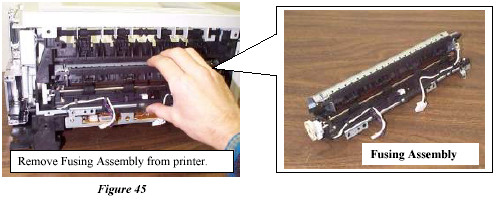
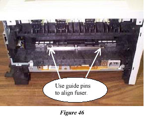
Remove the two screws that hold the Fusing Assembly to the printer and remove the Fusing Assembly from the Printer.
Replacing the Tray 2 Separation Pad Assembly
-
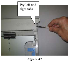
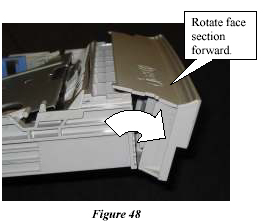
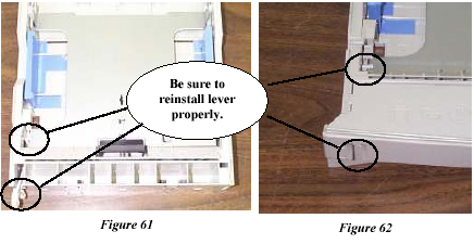
On the top front section of the Tray 2 paper cassette, pry the right and left lock tabs (Figure 47) with a small flat-blade screwdriver as you rotate the Cassette Face section forward, pivoting at the bottom edge (Figure 48) until the Cassette Face section comes loose.
-
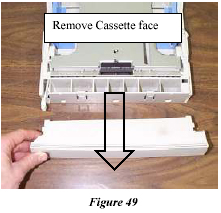
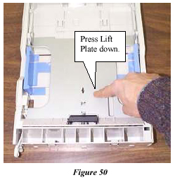
Remove the Cassette Face section and press the Paper Lift Plate down until the side latches “click” and the plate locks in a downward position.
-
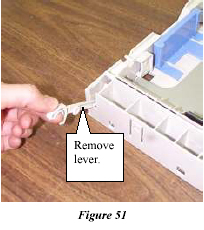
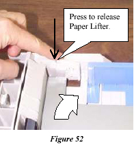
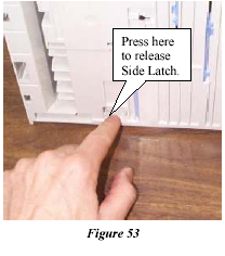
Remove the Paper Level Indicator Lever and release the Paper Lift Plate by pressing the trigger release arm on the left and right side latches .
-
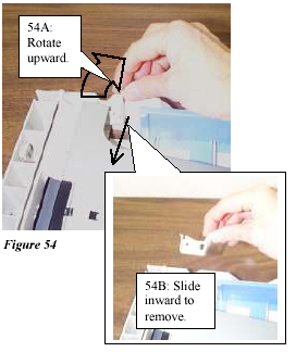
On the underside of the tray, press the release catch on both the left and right side latches so they can pivot freely. Rotate both the left and right side latches upward (Item 54A) then slide them inward to remove them (Item 54B).
-
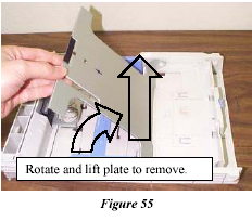
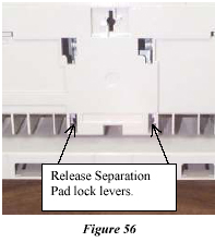
Rotate the Paper Lift Plate upward, then lift it straight up to remove it. Turn the tray over, and using a flatblade screwdriver, release the two lock levers for the Separation Pad Assembly.
-
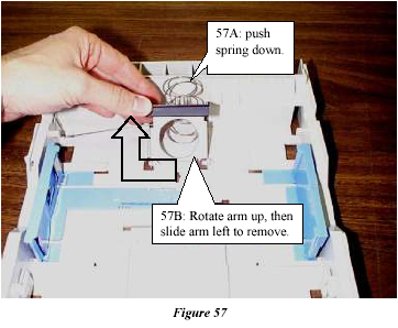
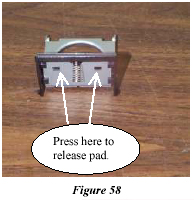
Press the Tray Lifter Spring down (Item 57A), then rotate the Separation Pad and metal Support Arm upward, then slide the arm left to remove it (Item 57B). Using a small, flat-blade screwdriver, carefully press the two lock levers to release the Separation Pad Assembly from the metal Support arm.
-
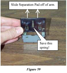
Slide the Separation Pad Assembly off of the metal Support Arm. Install the new Separation Pad Assembly by performing steps 9 through 1 in reverse order. Use rubber gloves in order to prevent damage to the Separation Pad Assembly.
Note: Save the spring and connect it to the new Separation Pad.
- Publisher: Precision Roller


 Ricoh A806-1295 Doc Feeder Paper Feed Belt


